
TL;DR:
- Complete mastery of parametric CAD relies on a deep understanding of parameters, constraints, and history management.
- Rigorous construction, reliable reference management, and stable naming are essential to avoid modeling errors.
- Fully leveraging parametric design allows for automation, acceleration, and securing the development of product variants.
Many engineers believe they master parametric CAD because they can model a part in 3D. In reality, the gap between basic use and truly effective exploitation is immense. What you don’t know about parameters, constraints, and history management can cost you hours of redesign, cascading errors, and extended time-to-market. This guide reveals the true foundations of parametric CAD, its often-misunderstood internal mechanisms, and practical precautions to make the most of it in your startup or industrial SME.
Table of contents
- Definition and Foundations of Parametric CAD
- Model Construction and Management: History and Features
- Parametric Features and Internal Representation of Geometries
- Topological Naming: The Hidden Obstacle of Parametric Design
- Automation, Reuse, and Operational Gains
- Our Perspective: Smart Parametric Design or Nothing
- Optimize Your Projects with Advanced CAD Solutions
- Frequently Asked Questions about Parametric CAD
Key Points
| Point | Details |
|---|---|
| Mastering Parameter Types | Understanding and structuring your parameters is the foundation of efficient and modifiable modeling. |
| Stabilizing References | Managing history and anticipating topological naming prevents breakage during complex modifications. |
| Automating Product Variants | Well-utilized parametric logic multiplies speed and reliability, while facilitating innovation. |
| Adopting the Right Methodology | Success depends more on the rigor of the CAD process than on the number of available software functions. |
Definition and Foundations of Parametric CAD
After establishing the necessity of true mastery, let’s detail the conceptual bases of parametric CAD.
Parametric design consists of defining entities using modifiable parameters, which allows for automatic updating of a model’s geometry when a parameter changes. Concretely, instead of drawing a part with fixed dimensions, you define it with variables: a length named “L_total”, a radius called “R_bend”, a thickness linked to a formula. Changing a parameter’s value then triggers the consistent update of the entire model.
This logic contrasts with direct geometric modeling, where each modification requires manual redrawing. For teams developing multiple variants of the same product, the difference is structural.
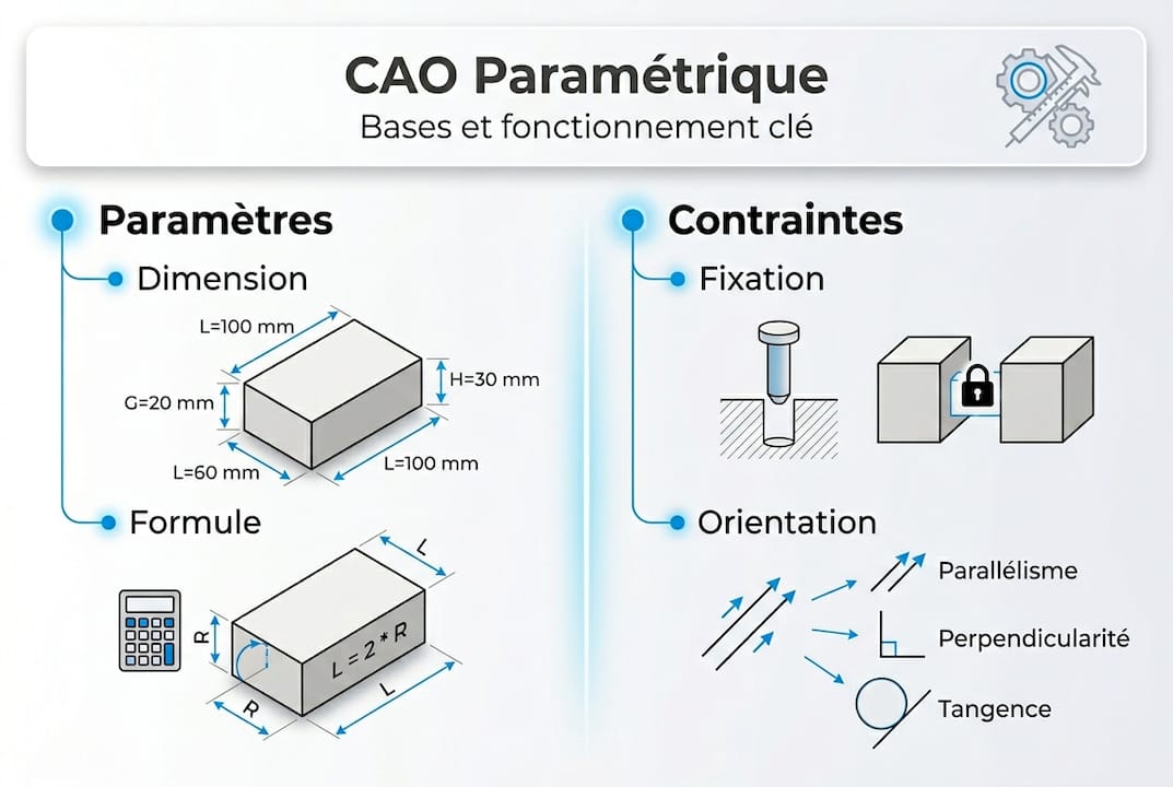
The three types of parameters to distinguish:
- Intrinsic parameters: These define properties internal to the entity itself, such as a length, an angle, or a radius. They are the most common in classic mechanical modeling.
- Cartesian parameters: These locate an entity in space based on a reference coordinate system. Useful for positioning components in an assembly.
- Situational parameters: These express a relationship between two entities, such as the distance between two faces or the angle between two axes. They are particularly powerful for constrained assemblies.
The concept of a constraint is often confused with that of a parameter. A constraint imposes a logical or geometric rule between entities, for example, “these two faces must remain coplanar” or “this edge must always be tangent to this cylinder.” Unlike parameters, constraints are not freely modifiable numerical values: they lock a relationship. A well-constructed model combines flexible parameters and judiciously chosen constraints.
| Type | Nature | Example |
|---|---|---|
| Intrinsic Parameter | Modifiable Value | Length = 150 mm |
| Cartesian Parameter | Position in Space | X = 25 mm, Y = 0 mm |
| Situational Parameter | Relationship between Entities | Distance between two axes |
| Constraint | Geometric Rule | Coplanarity, tangency |
To make the right choices upstream, it is useful to rely on a selection of innovative CAD tools adapted to the real needs of startups and industrial SMEs. Mastering these fundamentals avoids construction errors that often become apparent late, at the time of the first major model update.
Model Construction and Management: History and Features
Understanding parameters lays the groundwork, but the true value of parametric CAD lies in the systematic construction of models.

In mechanical parametric CAD, models built with history record each operation in a feature tree. Each feature corresponds to a precise operation: a sketch, an extrusion, a hole, a fillet. This tree constitutes the living memory of the model. Modifying an upstream feature can affect all downstream features that depend on it.
Typical steps for creating a solid parametric model:
- Define the hierarchy of master parameters: Identify the driving dimensions that will govern all others. For example, the total length of a housing can drive the spacing between holes.
- Create constrained sketches: Each sketch must be fully constrained, with no residual degrees of freedom. An under-constrained sketch generates unpredictable behavior during updates.
- Apply features in logical order: Start with the basic shape (main extrusion), then add details (chamfers, fillets, threads). The order has a direct impact on model stability.
- Explicitly name each feature: Instead of keeping “Extrusion1”, rename it to “Main_Body” or “M6_Mounting_Hole”. This facilitates reading the tree and future maintenance.
- Document parameter relationships: A clear parameter table, integrated into the file, allows another engineer to take over the model without having to rediscover everything.
To go further in documentary rigor, knowing how to document a CAD project is a skill as critical as modeling itself. Similarly, structured CAD file management prevents version loss and team conflicts.
External reference management deserves special attention. When a feature relies on geometry external to the current sketch (an existing edge, a face of another body), this reference can break during a modification. This type of error, often insidious, blocks model reconstruction at the worst possible moment.
Pro Tip: Systematically enable the display of external relationships in your software and audit them before each major update. Prefer references to fixed reference planes rather than edges or faces that may change names during a tree modification.
Parametric Features and Internal Representation of Geometries
Mastering structuring also means understanding the operational tools available.
Parametric CAD is typically expressed via “features,” which are named operations carrying a design intent. Each feature transforms or adds material according to precise rules. Here are the main categories:
- Extrusion (Boss/Cut): Projects a 2D sketch over a defined distance. This is the basic feature of all solid modeling.
- Revolution: Rotates a profile around an axis. Ideal for revolved parts such as shafts, bushings, or covers.
- Sweep: Extrudes a profile along a curved path. Used for pipes, rails, or complex profiles.
- Loft: Creates a surface or solid between several distinct profiles. Useful for aerodynamic or ergonomic shapes.
- Shell: Hollows out a solid while maintaining a constant wall thickness. Essential in plastic design and molding.
- Fillet/Chamfer: Softens sharp edges for functional or aesthetic reasons.
Internally, parametric CAD software relies on two main mathematical representations of geometries:
| Representation | Principle | Main Advantage |
|---|---|---|
| B-Rep (Boundary Representation) | Describes the solid by its faces, edges, and vertices | Precision and topological integrity |
| NURBS | Curves and surfaces defined by control points | Flexibility for organic shapes |
B-Rep is the standard in industrial mechanical design. It guarantees absolute precision on volumes and allows Boolean operations (union, subtraction, intersection) without approximation. NURBS are mainly used for complex surfaces, particularly in automotive design or aeronautics.
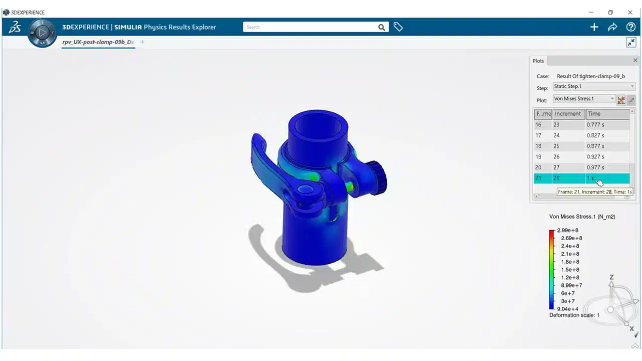
“The geometric precision of a parametric model is not just an aesthetic matter: it determines the validity of resistance simulations, thermal analyses, and machining ranges.”
To go further on effective 3D modeling strategies, proven methods exist to structure your models according to the complexity of your parts. Professionals who combine these techniques with advanced 3D modeling approaches obtain more robust and more easily exploitable models downstream in the development process.
Topological Naming: The Hidden Obstacle of Parametric Design
After classic functionalities, let’s address a challenge that is often underestimated but crucial for long-term reliability.
The Topological Naming Problem is one of the most underestimated problems in parametric CAD. It refers to the instability of names automatically assigned to faces, edges, and vertices of a model during modifications to the construction tree. Concretely: you add a fillet to an edge. You then modify an upstream feature that changes the numbering of the edges. The software can no longer find the original edge, and your fillet moves, disappears, or causes a reconstruction error.
This problem potentially affects all parametric CAD software, to varying degrees. It is particularly visible in complex operation sequences involving fillets, repeated holes, or patterns.
Examples of typical errors due to topological naming:
| Situation | Consequence |
|---|---|
| Reordering features in the tree | Fillet references point to the wrong edge |
| Deletion of an intermediate extrusion | Dependent holes “jump” to another face |
| Adding a feature before a pattern | The pattern recalculates on a geometry different from the initial intent |
| Modification of the number of instances in a pattern | Downstream features lose their references |
Solutions exist. Modern software develops persistent naming systems (also called “mapped names” via mechanisms like ElementMap or TopoShape). The idea is to link each face or edge to a stable identifier based on its logical origin in the construction tree, rather than a volatile numerical index.
Pro Tip: For your critical models, apply fillets and chamfers at the very end of the construction tree, after all main shape operations. This drastically reduces exposure to topological naming errors. Also, plan for the stability of your references from the initial design phase of features, not as a post-correction.
The good news: a rigorous approach to assembly optimization naturally integrates these best practices for topological stability, by limiting cross-references between components to the strict minimum.
Automation, Reuse, and Operational Gains
Finally, let’s move on to the application dimension and the performance levers offered by well-utilized parametric design.
Parametric logic serves to automate the updating of variants and to adapt existing models without rebuilding everything. This is where the return on investment becomes concrete for a startup or industrial SME.
Steps to implement effective parametric automation:
- Identify master parameters: What are the variables that truly differentiate your product variants (length, diameter, material, wall thickness)?
- Create a configuration table: In SOLIDWORKS, the “Design Table” tool allows you to control dozens of configurations from an Excel spreadsheet integrated into the file.
- Validate each configuration: All variants must be rebuilt without error before being validated. A broken configuration in production is costly.
- Associate ranges and bills of materials: Each configuration must automatically generate the correct Bill of Materials (BOM) and associated drawings.
📊 Key Point: According to industry data, teams that fully leverage parametric logic in their models reduce their variant design times by 40 to 60% compared to a repeated direct modeling approach.
Limitations and precautions not to ignore:
- A very complex parametric model can become difficult to maintain if the parameter hierarchy is not documented.
- Formulas between parameters can create circular loops or conflicts if not carefully organized.
- Reusing a parametric model in a context for which it was not intended can generate invalid geometries.
- Automation does not replace engineering judgment: each generated variant must still be verified by an expert.
To anticipate developments in these practices, follow the CAD innovations 2026 that are transforming how teams manage variants and model reuse. Approaches such as real-world model adaptation cases show that the robustness of a parametric system is always tested under real conditions, not just in simulation.
Our Perspective: Smart Parametric Design or Nothing
We work with dozens of design teams in startups and industrial SMEs. What we regularly observe is that most problems related to parametric CAD do not stem from a lack of features in the software. They come from an insufficiently anticipated construction methodology.
A practical approach in engineering recommends establishing a clear parameter hierarchy from the outset, even before starting to model. This is a reflex that too few teams develop, often because deadline pressure pushes them to model quickly rather than well.
The trap of “everything automatable” is real. A poorly designed parametric model that automatically generates invalid variants causes more damage than a simple model rebuilt manually. Parametric design is a multiplier: it amplifies good design decisions, but also bad ones.
Our conviction: the value of parametric CAD rests 70% on the quality of the method and 30% on mastery of the tool. Investing in the PDM function and parametric management allows this methodological investment to be structured across the entire organization, not just for an isolated engineer.
Optimize Your Projects with Advanced CAD Solutions
To take action or further your expertise, rely on recognized experts. At Ohmycad, we support design teams in startups and industrial SMEs in adopting and optimizing their parametric CAD tools, whether it’s SOLIDWORKS, CATIA, or the 3DEXPERIENCE platform.
Whether you wish to master 3D visualization in CAD to better communicate your designs, or explore the benefits of cloud CAD for effective remote collaboration, our experts are here to guide you. We help you get started on the right foot, with solutions tailored to your profile and product development goals. Contact us for personalized support.
Frequently Asked Questions about Parametric CAD
What is a parameter in a CAD model?
A parameter is a modifiable numerical data that defines a geometric or functional characteristic of a modeled entity. We distinguish between intrinsic, Cartesian, and situational parameter types, depending on the nature of the relationship they express.
Why do we talk about constraints in addition to parameters?
Constraints impose rules or a logical relationship between entities, which guides or locks certain parameter modifications. Unlike parameters, non-modifiable constraints define fixed relationships such as tangency or coplanarity between geometric elements.
What is the purpose of history management in parametric CAD?
It allows for retrieving and modifying each step of a model’s creation, ensuring consistency during evolutions. Models with history record each operation in a feature tree that can be replayed and modified at any time.
How to avoid errors related to topological naming?
By using persistent naming functions and anticipating the stability of references from the design of critical features. The solution involves persistent names via ElementMap, which associate each topological entity with a stable identifier independent of automatic numbering.
Does parametric CAD truly accelerate product development?
Yes, by automating the creation of variants and facilitating model reuse, it significantly reduces design times. Parametric logic for variants allows existing models to be adapted quickly, without rebuilding each version from scratch.