
TL;DR:
- A structured, tailored workflow significantly reduces design time.
- Mastering the key steps, from needs definition to validation, optimizes performance.
- A culture of questioning and automation boosts CAD productivity.
In your design projects, how much time does your team lose on tasks that could be reduced to a few seconds? Poorly structured modeling can turn a simple operation into a time-consuming nightmare: applying fillets early on simple shapes can cut a computation time of more than an hour down to a few seconds for 400 cavities. This guide offers practical methods, proven tools, and directly applicable tips to make your CAD workflow more reliable and reclaim valuable time on every project.
Table of contents
- Preparing an efficient modeling workflow: essential prerequisites
- Key steps for an optimized CAD workflow
- Interface customization and automation: productivity accelerators
- Verification, feedback, and continuous improvement
- Our perspective on the future of efficient modeling
- Go further with our CAD resources and solutions
- Frequently asked questions
Key Points
| Point | Details |
|---|---|
| Structured preparation | Proper workflow preparation and clear file organization are the foundation of future efficiency. |
| Automation | Using shortcuts, macros, and customizations can increase productivity by 20 to 30%. |
| Smart sequencing | Placing heavy operations at the end or automating them drastically reduces computation times. |
| Feedback | Continuous improvement relies on collective analysis and rapid correction of workflow weak points. |
Preparing an efficient modeling workflow: essential prerequisites
Now that you understand what is at stake, let us move on to laying the groundwork that makes all the difference. Even before you open your software, the quality of your workflow depends on decisions made upstream. Neglecting this phase is like building on sand.
Identify needs and set project objectives
The first mistake rushed teams make is jumping straight into modeling without clearly defining the project scope. What deliverables are expected? What tolerances are required? What exchange formats will be needed with your subcontractors or customers? Answering these questions upfront avoids costly rework.
An internal specification document, even a brief one, helps frame expectations and align the entire team on the same objectives from day one. This reference document also helps justify technical choices during project reviews.
Choosing the right software for your SME
Tool selection is fundamental. For general mechanical design in SMEs, SOLIDWORKS is the preferred choice over Inventor when the ecosystem is not tied to Autodesk. Inventor remains relevant if your company already uses other Autodesk solutions such as AutoCAD or Vault. Solid Edge, for its part, appeals thanks to its direct modeling power, but it is still less widespread among French SMEs.
Here is a quick comparison table to help you choose:
| Software | Strengths | Ideal for |
|---|---|---|
| SOLIDWORKS | Easy to learn, large community | General mechanical SMEs |
| Inventor | Autodesk integration, data management | SMEs already equipped with Autodesk |
| Solid Edge | Direct modeling, performance | Advanced design offices |
| CATIA | Large complex parts, aerospace | Large enterprises, aerospace sector |
Consult our resources on 3D modeling methods to refine this choice based on your industry.
Define a clear naming convention and centralize references
Rigorous file organization is often underestimated. Naming your parts, subassemblies, and drawings correctly from the outset prevents endless searches and version conflicts. Adopt a naming convention shared by the entire team, documented in a reference file accessible to everyone.
Key items to define before you start:
- Naming convention: project reference + part type + version (e.g., PRJ001_BODY_A01)
- Folder structure: separate raw parts, assemblies, and drawings
- Revision management: define who approves each revision and how it is tracked
- Component libraries: centralize standard parts so you do not recreate them for every project
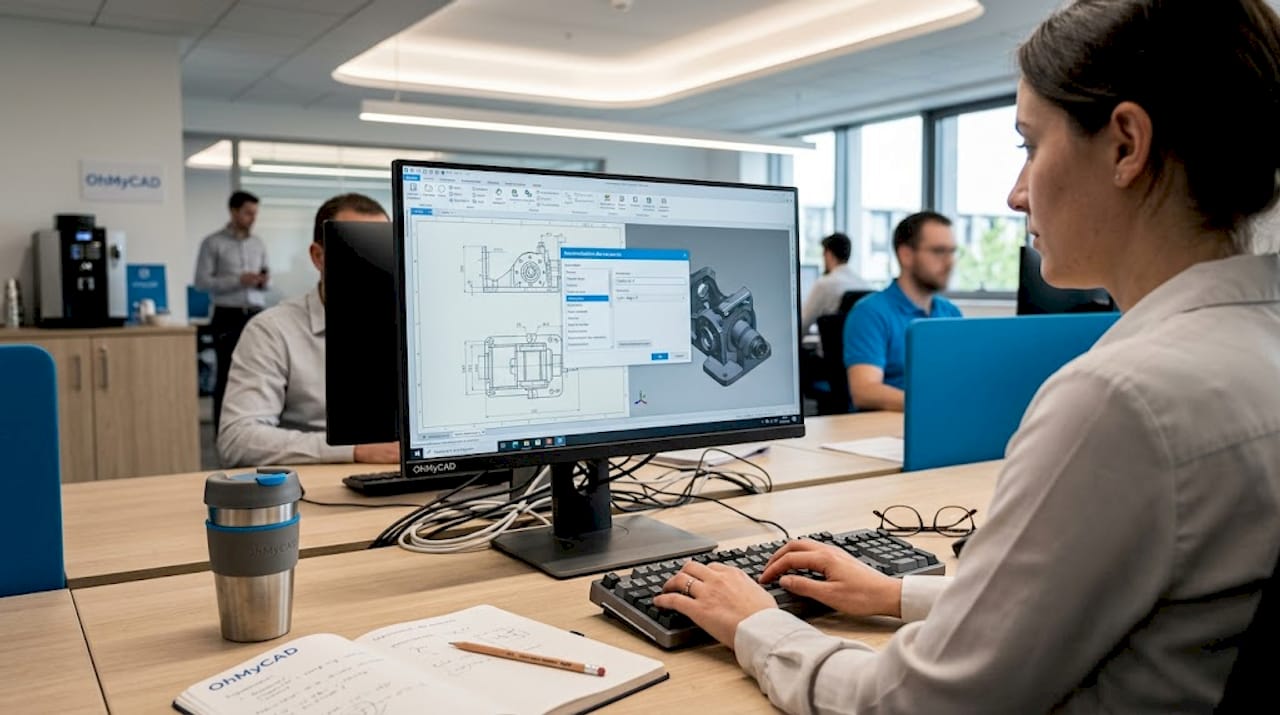
Taking a look at a concrete example of a CAD interface often helps you understand how to organize your workspace visually.
Pro tip: Customize your interface as soon as you install the software. Place the tools you use most often in your quick access toolbar, remove unnecessary menus, and create dedicated workspaces by project type. This initial setup, done in 30 minutes, will save you several hours per week over time.
Key steps for an optimized CAD workflow
Once the prerequisites are in place, the goal is to follow, step by step, a truly high-performance workflow. The approach below applies whether you use SOLIDWORKS, CATIA, or any other parametric software.
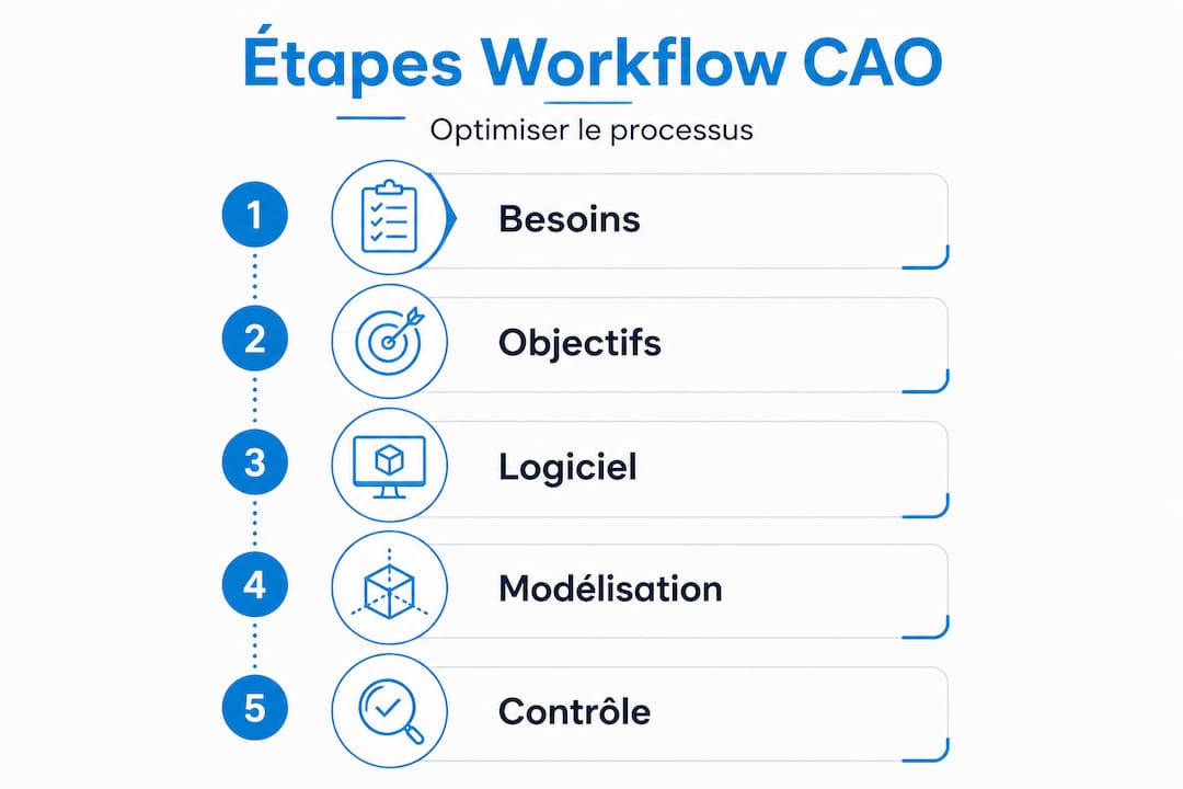
The recommended step-by-step method
- Define the assembly structure: create the main assembly tree and identify functional subassemblies before any part modeling
- Establish guiding sketches: create master sketches with key functional dimensions that will drive the entire parametric design
- Model the main shapes: create the base volumes first, reserving fine details for later steps
- Add detail features: fillets, chamfers, threads, and other details come last, once the main geometry is validated
- Check interferences: run an interference analysis on the assembly before going further
- Document and annotate: fill in part properties, create drawings and associated BOMs using our guide to document a CAD project
- Validate with stakeholders: organize a formal review before moving to manufacturing
This sequence may seem obvious, but in the reality of SMEs, steps 4 and 3 are often reversed, which generates considerable rebuild times. Procedural modeling strategy confirms that moving heavy operations to the end of the process drastically reduces computation times.
Linear workflow vs. iterative workflow: which should you choose?
| Criterion | Linear workflow | Iterative workflow |
|---|---|---|
| Best suited to | Defined projects, fixed specifications | Evolving projects, innovation |
| Main risk | Rigidity if specs change | Version management complexity |
| Setup time | Short | Longer, but more robust |
| Final quality | Good if the need is well defined | Excellent, better suited |
| Recommended for SMEs | Production projects, minimal changes | R&D, new products |
For complex assemblies, an iterative workflow is generally more suitable, as it allows you to incorporate field feedback in each design loop.
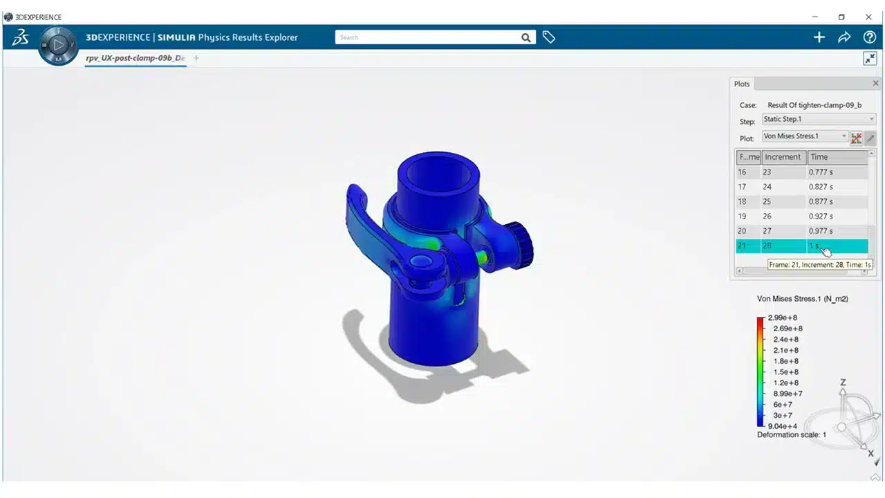
⚠️ Point to note: One of the most costly mistakes is applying heavy operations (fillets on hundreds of edges, complex shells) before validating the base geometry. A late change to the main shape then forces you to redo all those operations. Build the skeleton first, then dress it.
Pro tip: Group all your detail features (fillets, chamfers, textures) in a dedicated feature folder in the design tree. This way, you can temporarily suppress them to lighten the model during simulation calculations, then restore them with a single click.
Interface customization and automation: productivity accelerators
Beyond the method, customization and automation create an additional advantage for the entire team. This level of optimization is often overlooked by SMEs getting started, even though it is one of the most powerful levers available.
Configure the interface to match your real needs
Every modern CAD package offers extensive customization options. The goal is simple: reduce the number of clicks required to access the functions you use every day. Customizing keyboard shortcuts and the interface can increase productivity by 20 to 30%, according to feedback from professional AutoCAD and SOLIDWORKS users.
This gain may seem modest in absolute terms, but in practice, for a team of 5 engineers working 35 hours per week, it represents between 35 and 52 hours of work recovered every week. Over a year, that is the equivalent of several additional person-weeks, without hiring.
Key customizations to implement
Here are the priority settings to enable from the outset:
- Custom keyboard shortcuts: assign the most frequent functions to single keys (e.g., “E” for extrude, “R” for revolve)
- Context toolbars: display only the relevant tools depending on the type of operation in progress
- Startup templates: create part and assembly templates with your default settings (units, standard materials, pre-filled custom properties)
- Custom libraries: integrate your recurring components (fasteners, bearings, profiles) into a one-click-access library
- Display profiles: configure views and levels of detail suited to each project phase
To go further in selecting the right tools for your organization, explore our selection of innovative tools for SMEs.
Macros and scripts: automating repetitive tasks
Macros are recorded instruction sequences that automatically reproduce a series of actions. In SOLIDWORKS, they are written in VBA or C#, and can, for example, batch-rename parts according to a convention, automatically export files in multiple formats, or generate standardized BOM tables.
A concrete example: a company that regularly exports its parts in STEP, STL, and PDF for subcontractors can automate this triple export in a single action. What used to take 8 minutes per part is reduced to 20 seconds. Over 50 parts per week, that is nearly 6 hours recovered.
Pro tip: Systematically back up your user profiles to a shared server or a secure cloud space. In the event of a workstation change, a software update, or onboarding a new team member, you can restore the complete working environment in just a few minutes. See our article on CAD innovations 2026 to discover the new automation features available.
Verification, feedback, and continuous improvement
Once automation is in place, the final step is to ensure the workflow is effective and to sustain the gains. A workflow is never set in stone. It evolves with your projects, your teams, and your tools.
Verification and control methods
Verification is not limited to reviewing a model alone. The most effective approaches combine several levels of control:
- Cross-check: a colleague who did not model the part reviews it with a fresh perspective, following a formalized verification checklist
- Formal peer reviews: organize a short meeting (30 minutes maximum) to validate modeling choices before moving to drawings
- Interference and simulation tests: use tolerance analysis tools to detect geometric issues before manufacturing
- Property verification: ensure all metadata (material, mass, reference) is correctly filled in
Examples in the automotive industry show that companies that systematize these checks significantly reduce their non-conformance rates.
Measuring impact: before/after indicators
To demonstrate the value of workflow optimization, you need to compare tangible indicators. Here is a typical tracking table:
| Indicator | Before optimization | After optimization | Target objective |
|---|---|---|---|
| Average modeling time per part | 4h30 | 2h45 | Less than 2h |
| Number of rework iterations per project | 6 | 2 | Less than 2 |
| Drawing error rate | 12% | 4% | Less than 3% |
| Multi-format export time | 8 min/part | 20 sec/part | Less than 30 sec |
| Team satisfaction (scale 1 to 5) | 3.1 | 4.3 | 4 or higher |
The SolidWorks vs. Inventor comparison confirms that choosing the right tool combined with an appropriate workflow delivers measurable results on these indicators.
Typical corrective actions to plan
During your workflow reviews, you will frequently encounter these improvement areas:
- Rework the assembly tree structure when load times become excessive
- Update templates after each change in customer standards or industry norms
- Archive old versions rather than letting them clutter the active workspace
- Train new hires on the internal workflow during their first week
- Document special cases in an internal wiki or collaborative space
Our perspective on the future of efficient modeling
Based on these technical findings, let us take a closer look at what truly makes the difference in the field. After supporting dozens of SMEs in implementing their CAD workflows, we observe a recurring paradox: the least efficient teams do not lack tools. They often have too many.
The real barrier to performance is not technical. It is resistance to questioning what already exists. A process that has been in place for three years, even an inefficient one, benefits from powerful inertia. No one wants to be the person who challenges the way the entire team works.
However, the most spectacular gains we have observed always came from radical simplification. A customer in mechanical manufacturing removed two intermediate validation steps that had been created to fix a problem resolved long ago. Result: three days saved on every product development cycle, with no additional software spend.
Complexity naturally accumulates in workflows. Each one-off problem generates a workaround procedure. These procedures stack up until no one understands why certain steps exist. This is what we call “false complexity”: an invisible workload that slows everything down without adding any value.
We believe that true CAD modeling performance is built on two pillars: a solid method and a culture of continuous questioning. CAD innovations 2026 bring ever more powerful features, but it is the teams that regularly dare to re-examine how they work that truly benefit from them.
Challenging every step of your workflow every six months is not a waste of time. It is the most profitable investment you can make for your team.
Go further with our CAD resources and solutions
For those who want to take their optimization all the way, several expert resources are available.
At ohmycad.com, we support SMEs and project teams in structuring and optimizing their CAD workflows, from software selection through to production release. Our experts help you configure your environment, choose your SOLIDWORKS or CATIA licenses, and implement automations tailored to your real-world needs. Discover our guide to 3D visualization to enhance your design reviews, explore the possibilities offered by cloud-based CAD via the 3DEXPERIENCE platform, and strengthen your organization with our advice on advanced file organization. Contact us for a no-obligation discussion with one of our experts.
Frequently asked questions
Which modeling software is best suited to an SME?
For general mechanical design in SMEs, SolidWorks is often preferred for its ease of use and community, while Inventor integrates better in environments already equipped with Autodesk solutions.
What tangible gains can you expect from customizing the CAD interface?
Customizing the interface and keyboard shortcuts can increase productivity by 20 to 30%, which represents several person-weeks recovered over the year for a standard-sized team.
What are the main pitfalls to avoid in a modeling workflow?
Poor sequencing of operations (adding details before validating the base geometry) and the lack of collective feedback are the two most common causes of time loss in SME CAD workflows.
When should you use procedural modeling strategy?
For large-scale or repetitive projects, procedural modeling can reduce computation time from more than an hour to a few seconds for complex geometries such as 400 cavities. It is particularly well suited to production parts or molds.
How can you assess whether a new workflow is truly effective?
You need to compare measurable indicators before and after implementation (modeling time, number of rework iterations, error rate), and organize collective feedback sessions every quarter to continuously refine practices.