
TL;DR:
- Surface modeling is relevant to both aeronautics and product design, requiring mastery of surface continuity. It offers essential aesthetic precision for demanding applications such as automotive, aeronautics, or ergonomics, while also being a strategic differentiator. The use of specialized tools like CATIA, Alias, or Rhino allows for achieving high levels of quality, indispensable for ensuring manufacturability and final aesthetics.
Many engineers believe that surface modeling only concerns industrial designers or automotive body designers. However, if you work on free-form parts, aeronautical hulls, or even medical equipment, you are already dealing with surface-related issues without always naming them as such. This guide offers a clear and operational vision of what surface modeling truly is, why it is essential in complex projects, and how to approach it effectively with modern CAD tools, particularly SOLIDWORKS and CATIA.
Table of contents
- Definition and Principles of Surface Modeling
- Use Cases and Industry Benefits
- Key Tools, Methods, and Software
- Best Practices and Pitfalls to Avoid in Surface Modeling
- Why Surface Modeling Remains a Differentiator in Advanced Design
- Take Action with Our Advanced CAD Solutions
- Frequently Asked Questions About Surface Modeling
Key Points
| Point | Details |
|---|---|
| Conceptual Foundations | Surface modeling allows for the creation of complex shapes from free-form surfaces in CAD. |
| Industry Benefits | Projects where aesthetics or aerodynamics are essential require this surface approach. |
| Success Criteria | Controlling geometric continuity and using appropriate tools ensures the quality of the final result. |
| Tool Selection | Choosing the right software based on complexity and industry optimizes the design process. |
| Gaining Competitive Advantage | Surface mastery durably differentiates innovative design offices from competitors. |
Definition and Principles of Surface Modeling
Surface modeling is based on constructing shapes from free-form surfaces, meaning geometries that do not define a closed volume but rather a precisely controlled three-dimensional envelope. Unlike solid modeling, which starts from a closed volume and modifies it through Boolean operations, surface modeling builds the shape “from the outside in.” It involves generating surfaces, connecting them, and controlling them point by point.
This approach is essential whenever form is as important as function. Here are the fundamental differences between the two approaches:
| Criterion | Solid Modeling | Surface Modeling |
|---|---|---|
| Starting Point | Closed Volume | Free-form Surfaces |
| Form Flexibility | Limited to Primitives | Very High (NURBS, Bézier) |
| Aesthetic Control | Low to Medium | Very Precise |
| Primary Domain | Standard Mechanical Parts | Bodywork, Hulls, Design |
| Quality Analysis | Dimensional Tolerances | Curvature Continuity, Tangency |
| Compatibility | Direct with CAM | Often Requires Conversion |
Effective 3D modeling methods cover both approaches, but surface modeling requires specific expertise in geometric quality. In particular, the central challenge is to master continuity levels:
- G0 Continuity: simple contact between surfaces, without a smooth blend
- G1 Continuity: tangency, surfaces meet without a visible angle
- G2 Continuity: identical curvature on both sides of the blend, a criterion required for “Class A” surfaces
- G3 Continuity: continuous curvature variation, used in the most demanding projects
Parametric CAD facilitates the management of these levels by associating each surface with modifiable parameters. The challenge of geometric continuity, whether curvature or tangency, is central in “free-form” and “Class A” environments. Without this mastery, even a beautiful shape on screen can prove catastrophic during tooling or final rendering.
Use Cases and Industry Benefits
Having laid the groundwork, let’s see in practice where and how surface modeling truly makes a difference in industry. It is indispensable in three major areas:
Automotive: a vehicle’s bodywork combines simultaneous requirements for aerodynamics, brand design, and manufacturability. Poor surface continuity is immediately visible under glancing light or after painting. Automotive paint finish mercilessly reveals surface defects that the digital model might have overlooked. A car fender poorly connected to a hood, even by 0.1 mm, is visible to the naked eye.
Aeronautics: aircraft fuselages combine critical aerodynamic constraints with tight tolerances. A bulge or a misaligned surface can alter airflow and impact performance or certification.
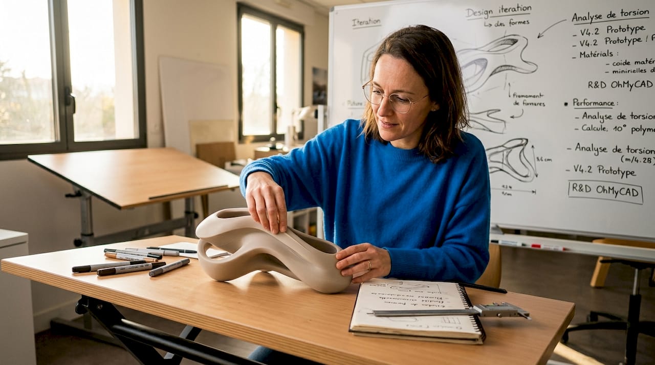
Product Design: helmets, watches, connected objects, medical devices. These products require impeccable surfaces for ergonomic, aesthetic, and sometimes regulatory reasons.
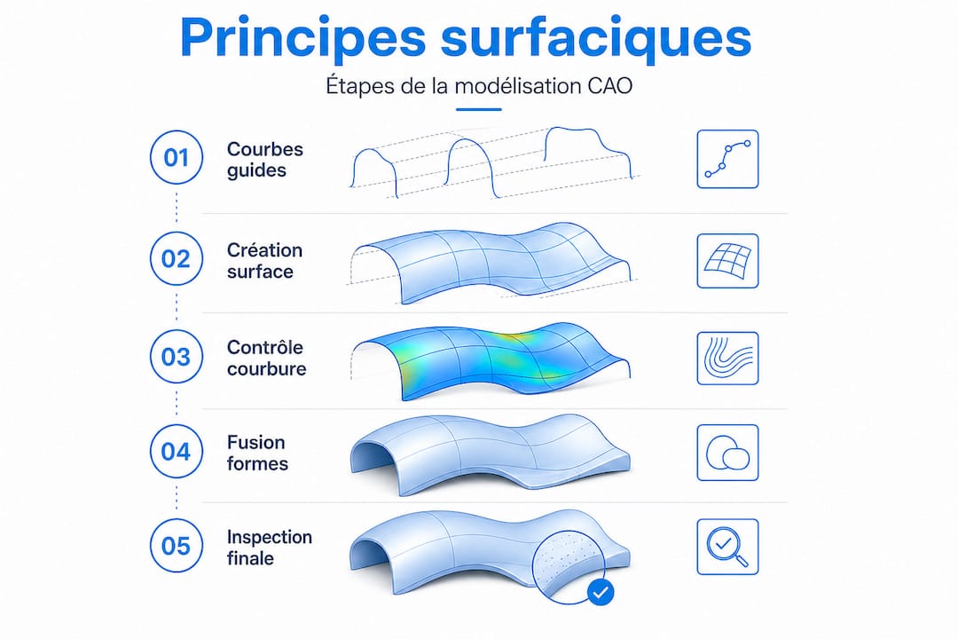
Here are the key steps to start a surface modeling project:
- Define the form intent: 2D sketches, physical mock-ups, or 3D scanning data serve as initial references.
- Build guiding curves: NURBS (Non-Uniform Rational B-Spline) curves guide the creation of the initial surfaces.
- Generate primary surfaces: each main surface is created individually, with a minimum of control points.
- Connect surfaces: junctions are carefully crafted to meet the required continuity (G1 minimum, G2 ideal).
- Analyze quality: zebra stripes, curvature analysis, isophotes to visualize and correct defects.
- Validate and convert: convert to solid or export to CAM as needed for production.
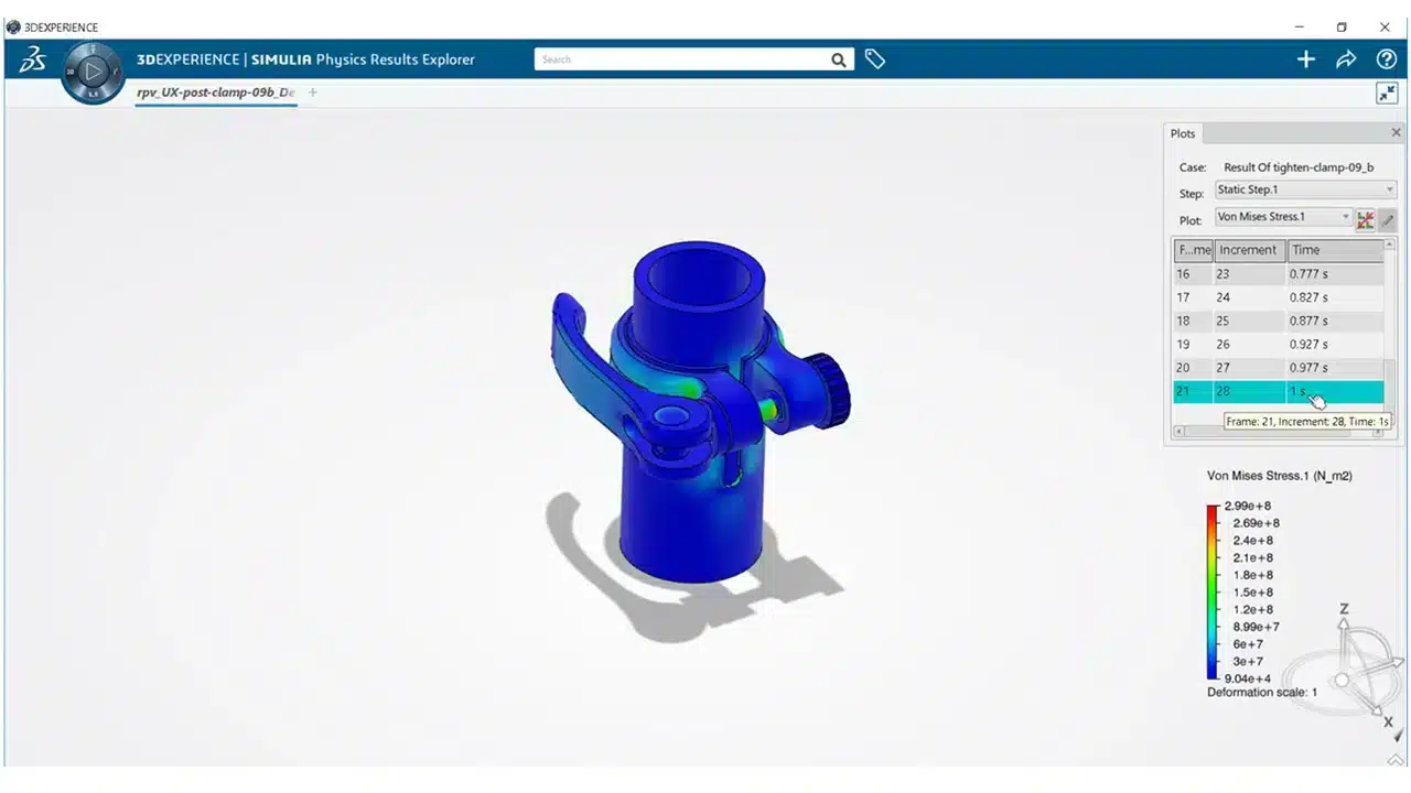
An efficient modeling workflow integrates these steps iteratively, as adjustments are inevitable. Automotive projects on 3DEXPERIENCE perfectly illustrate how this iteration is managed at an industrial scale, with multidisciplinary teams sharing and validating surfaces in real-time.
“The quality of a surface is judged not only by its geometry but by how light passes through it. A defect invisible in wireframe view becomes obvious under glancing light or in a zebra analysis.”
Curvature and zebra analysis precisely help avoid visual continuity defects and “highlight flow” issues that dimensional measurement tools do not detect.
Pro tip: anticipate risk areas from the guiding curve design phase. Star points (three or more surfaces meeting at a single point) are classic pitfalls: minimize them as much as possible and address them last, after all adjacent surfaces have been stabilized.
Key Tools, Methods, and Software
Understanding the uses naturally leads to exploring the appropriate tools and methods for excelling in surface modeling. The market offers several solutions, each positioned in a specific segment.
| Software | Surface Specialty | Target Sector | Complexity Level |
|---|---|---|---|
| CATIA | Class A, Complex Surfaces | Automotive, Aeronautics | Very High |
| SOLIDWORKS | Hybrid Solid/Surface | SMEs, Product Design | Medium to High |
| Alias (Autodesk) | Class A Industrial Design | Automotive, Design | Very High |
| Rhino 3D | Free-form, Rapid Prototyping | Design, Jewelry, Architecture | Medium |
| ICEM Surf | Pure Class A, Tooling | Premium Automotive | Expert |
Selection criteria depend on several factors:
- Target Industry: Premium automotive requires CATIA or Alias for Class A surfaces; an SME in product design will often be well served by SOLIDWORKS or Rhino.
- Budget: CATIA licenses represent a significant investment, justified by high-value-added projects.
- Form Complexity: For very free-form geometries, NURBS and Bézier patch tools offer the necessary flexibility that solid modelers cannot achieve.
- Integration into an existing ecosystem: If your design office already works with SOLIDWORKS, integrated surfacing modules offer real time savings without changing environments.
To go further on rendering and visualization, 3D visualization types play an important role in validating surfaces before production. And for large-scale industrial projects, CATIA for industrial projects remains the undisputed benchmark, particularly thanks to its modules dedicated to continuity management and surface quality analysis.
From a methodological standpoint, three approaches structure surface practice:
- NURBS: the basis of almost all modern software, offering precise curvature control via weighted control points.
- Bézier Patches: ideal for local shapes, easy to master for precise blends.
- Subdivision Surfaces: increasingly popular in creative design, it allows for natural organic shapes but requires retopology for production.
Best Practices and Pitfalls to Avoid in Surface Modeling
Equipping yourself with the right software is not enough: let’s illustrate the essential practices and reflexes for successful surface projects. The most costly errors in surfacing are not gross form errors, but subtle continuity defects that only become apparent during the manufacturing or rendering phase.
Here is a sequence of best practices to systematize:
- Control continuity from curve construction: even before creating surfaces, verify that your guiding curves meet the required continuity levels. A poorly connected curve generates an irreparable surface.
- Limit the number of control points: the temptation is to multiply points to “refine” the shape, but this creates surfaces that are difficult to analyze and connect. Fewer points mean more control.
- Build in logical order: primary surfaces first, secondary blends next, complex junctions last. Never start with difficult areas.
- Systematically use analysis tools: geometric continuity and zebra analysis are crucial to avoid major defects that would go unnoticed until manufacturing.
- Document form intentions: annotate your models with the required continuity levels at each junction. This avoids misunderstandings during design reviews.
- Validate in real conditions: import your model into a rendering engine or use virtual studio lighting to identify visual imperfections that analytical tools might have missed.
For managing complex SOLIDWORKS assemblies, integrating surfaces into an assembly context requires particular attention to references and geometric constraints. A poorly referenced surface can create downstream conflicts that are very difficult to diagnose.
Common pitfalls to avoid:
- Star points: avoid having three or more surfaces meet at exactly the same point. Slightly shift the junctions to create binary blends that are easier to control.
- Over-modeling: wanting to model everything in a single surface is counterproductive. Break down complex shapes into simpler, more controllable patches.
- Forgetting manufacturability: a perfect surface in CAD can be impossible to demold or machine. Consult the tooling engineer from the surfacing phase.
Pro tip: systematically test your surfaces with at least three different inspection methods: isophote analysis (light lines), zebra analysis (reflected stripes), and curvature analysis (chromatic mapping). Each reveals a different type of defect, and their combination gives you a complete picture of the geometric quality.
Why Surface Modeling Remains a Differentiator in Advanced Design
Here’s a reality few articles frankly mention: surface mastery is not just a technical skill; it’s a strategic competitive advantage. In a context where many projects are outsourced or automated, the ability to design and validate Class A surfaces represents a rare value in the market.
In our support for design offices and industrial SMEs, we observe that teams who invest in surface training gain credibility with their clients. A clean, well-documented surface model, with explicitly controlled continuity levels, inspires confidence. It reduces back-and-forth during the validation phase and accelerates production.
But beyond operational efficiency, surface modeling allows for integrating dimensions that solid modeling often ignores: user experience, brand identity, functional aerodynamics. A product’s form communicates as much as its color or name. An ergonomic handle, a car fender with perfect reflections, an electronic casing whose edges disappear into the hand: all of this is built with surfacing, and it shows.
Conventional wisdom would suggest that these concerns are reserved for large corporations with dedicated teams. Our conviction is different. Even a startup or an SME designing a niche product can radically differentiate itself by investing in surface quality. The tools exist, training is accessible, and modern 3D modeling methods allow for achieving Class A levels without heavy infrastructure.
The challenge is not to wait for the competition to force this upskilling upon you. Investing in continuous training on the most advanced surfacing tools means empowering yourself to offer more than just functionality: to offer a complete product experience.
Take Action with Our Advanced CAD Solutions
You now have a clear vision of what surface modeling can bring to your projects. The question is no longer “why master surfacing,” but “how to progress concretely and quickly.”
At ohmycad.com, we support engineers and design offices in adopting the most suitable tools for their surfacing needs. Whether you want to access CATIA 3DEXPERIENCE solutions for demanding Class A projects, equip yourself with SOLIDWORKS certified hardware for an optimized work environment, or deepen your knowledge with our resources on advanced 3D modeling methods, our team is here to guide you toward the most relevant solution. Contact us for personalized support.
Frequently Asked Questions About Surface Modeling
What truly distinguishes surface modeling from solid modeling?
Surface modeling builds complex shapes from free-form surfaces, while solid modeling works with closed volumes suitable for standard mechanical parts. Surface modeling offers much finer control over aesthetics and geometric blends.
Why is curvature continuity so crucial in surfacing?
Curvature continuity ensures the absence of visual breaks between surfaces, which is essential for the aesthetics and quality of high-end products, particularly in automotive and jewelry. Without it, defects immediately appear under glancing light.
Which sectors primarily use surface modeling?
Surface modeling is central in automotive, aeronautics, product design, and jewelry to master complex shapes that combine functional and aesthetic requirements.
Is solid modeling software like SOLIDWORKS sufficient for all projects?
For complex and aesthetic geometries, modern analysis tools and specialized surfacing modules are indispensable in addition to standard solid functionalities. SOLIDWORKS integrates relevant surfacing capabilities, but Class A projects often require CATIA or dedicated tools.