
TL;DR:
- Choosing a CAD format is a crucial strategic decision to ensure compatibility, quality, and security during manufacturing. Native formats retain all design information but require a high level of trust, while neutral formats make sharing easier but may lose essential data. Rigorous file management, tailored to each process, helps optimize workflows and reduce the risk of delays or loss of intellectual property.
You have just finalized a 3D model in SOLIDWORKS and your manufacturer is asking for a STEP file. Your sheet metal partner is expecting a DXF. Your 3D printing provider is requesting an STL. And you no longer know where to start. This scenario is very common for startups and entrepreneurs in the product development phase. Choosing the right CAD file format is not purely a technical matter: it is a strategic decision that determines the quality of your exchanges, the reliability of your prototyping, and ultimately the success of your industrial project.
Table of contents
- Criteria for choosing a CAD file format
- Native formats: SOLIDWORKS, CATIA, and their uses
- Neutral and exchange formats: STEP, IGES, STL, DXF, DWG
- Comparison: advantages and limitations of CAD file types by workflow
- Practical situations: how to optimize your CAD file exchanges
- Our perspective: behind the file choice, more at stake than it seems
- To go further: discover our CAD resources and solutions
- Frequently asked questions about CAD file types
Key Points
| Point | Details |
|---|---|
| Native and neutral formats | Proprietary formats offer richer data, while neutral formats make sharing and manufacturing easier. |
| Choose based on workflow | Select the format based on the project context: prototype, manufacturing, subcontracting, or collaboration. |
| Loss of information | Converting a native file to a neutral format can result in the loss of parametric and assembly features. |
| Recommendations by process | STEP for CNC, STL/OBJ for 3D printing, DXF for sheet metal or 2D drawings to share. |
Criteria for choosing a CAD file format
Before choosing a format, you need to understand what drives that choice. Several factors come into play, and ignoring them can cost your startup time and money.
Here are the main criteria to assess:
- The nature of the project: is it a rapid prototype, a final part intended for production, or a complex assembly with multiple components?
- Compatibility with your partners: does your manufacturer or subcontractor use SOLIDWORKS, CATIA, Fusion 360, AutoCAD? Can they open your native files, or do they need a neutral format?
- Interoperability between software: not all CAD platforms speak the same language natively. Moving from one tool to another often requires conversion.
- Manufacturing requirements: choosing CNC vs 3D printing involves different formats, with distinct geometric and resolution constraints.
- Parametric management: do you want to keep the design history and relationships between features? This need strongly points toward native formats.
In practice, choosing the right format depends on the target process (CNC, sheet metal, 3D printing) and the partner’s ability to import the native or neutral format. This reality often forces you to juggle multiple formats depending on who you are working with.
To properly structure your workflow, also consider organizing your CAD files from the outset and documenting each step of your CAD project to avoid information loss during exchanges.
Pro tip: Before starting production or prototyping, always send a test file to your partner to validate compatibility. A failed conversion discovered too late can block an entire launch schedule.
Native formats: SOLIDWORKS, CATIA, and their uses
In CAD, the main distinction is between native (proprietary) formats and neutral or exchange formats. Native formats are created and used directly by a specific software package. They contain all design information.
SOLIDWORKS native formats:
- .SLDPRT: individual part file, with the full parametric feature tree
- .SLDASM: assembly file grouping multiple parts with their relationships and mates
- .SLDDRW: associative drawing linked to parts and assemblies
CATIA native formats:
- .CATPart: CATIA equivalent of SLDPRT, very rich in design data
- .CATProduct: CATIA assembly file with advanced reference management
- .CATDrawing: drawing format dedicated to CATIA
These formats offer remarkable information richness. You keep full parametrics, relationships between features, assembly constraints, and change history. This is a major advantage for iterating quickly on a design or correcting an issue without rebuilding everything.
The trade-off is real. A .SLDPRT file does not open directly in CATIA, and vice versa. If your subcontractor uses different software, conversion becomes necessary. To better qualify your 3D files before sending them, there are structured methods that help you avoid unpleasant surprises.
“Native formats guarantee full model fidelity, but create dependency on the source software. As soon as you leave that ecosystem, conversion is inevitable and potentially risky.”
Parametric CAD relies precisely on this richness of native formats. Losing that parametric data during export can force you to rebuild the model from scratch with a partner, which represents a significant cost for a startup.
Neutral and exchange formats: STEP, IGES, STL, DXF, DWG
Neutral formats are used for interoperability between different software packages and stakeholders. They are your 3D model’s passports to the outside world. Each one meets specific needs.
| Format | Type | Primary use | Advantages | Limitations |
|---|---|---|---|---|
| STEP (.stp) | Neutral solid 3D | CNC machining, subcontracting | Accurate geometry, highly compatible | Loss of parametrics |
| IGES (.igs) | Neutral surface 3D | Legacy software exchanges | Broad compatibility | Less effective than STEP |
| STL | 3D mesh | 3D printing | Universal standard | Not editable |
| OBJ / 3MF | Enhanced mesh | Advanced 3D printing | Colors, textures, multi-material | Less common |
| DXF | 2D vector | Sheet metal, laser cutting | Highly compatible | No solid 3D |
| DWG | AutoCAD native 2D | Drawings, documentation | Very widespread | Difficult outside AutoCAD |
Details of key formats:
- STEP (ISO 10303): this is the reference format for mechanical and industrial collaboration. All serious CAD software imports and exports it. It preserves solid geometry with high fidelity.
- IGES: older, it remains useful for certain specific exchanges, notably with legacy systems. However, it sometimes generates imperfect surfaces during conversion.
- STL: essential for 3D printing, it represents the model surface as triangles. Simple and universal, but entirely static. It is impossible to modify the object once exported.
- OBJ and 3MF: alternatives to STL for multi-color or multi-material prints. The 3MF format, developed by a consortium including Microsoft and Autodesk, is becoming increasingly popular.
- DXF: widely used for 2D drawing interoperability, it is the preferred format for sending cutting drawings to sheet metal workers or laser operators.
- DWG: AutoCAD’s proprietary format, often requested in technical documentation. Converting it to other formats can result in the loss of certain elements.
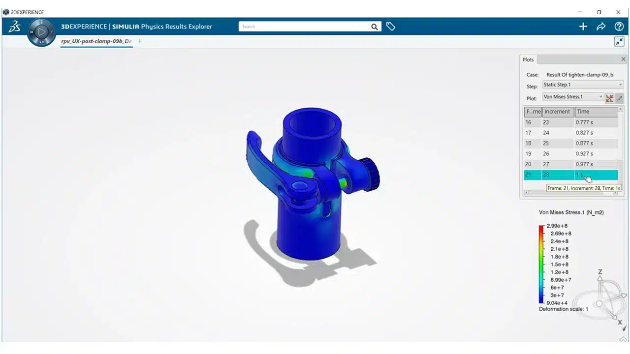
For combined CNC and 3D printing methods, the format choice must be anticipated from the design phase. 3D visualization in CAD can also help you visually validate the result before export.
Pro tip: Systematically export your model to STEP AND STL as soon as a version is validated. This covers the two most common use cases (machining and 3D printing) without having to redo the operation under pressure.
Comparison: advantages and limitations of CAD file types by workflow
Knowing the formats is not enough. You need to know which one to choose for your specific situation. Here is a startup-oriented summary.
| Situation | Recommended format | Why |
|---|---|---|
| Rapid 3D-printed prototype | STL or 3MF | Universal standard, accepted by all printing services |
| CNC machining with a subcontractor | STEP | Faithful solid geometry, compatible with all CAM software |
| Laser cutting or sheet metal | DXF | Universal 2D format for cutting machines |
| Exchange with an external engineering office | STEP or native format | Depending on the partner’s tools |
| Documentation and drawings | DWG or PDF | Depending on the client’s habits |
| Internal collaboration with the same software | Native (SLDPRT, CATPart) | Full preservation of parametrics |
For 3D printing, STL is the most common reference format based on a triangulated mesh, while STEP is preferred when you want to retain solid or parametric CAD geometry for industrial preparation or mechanical collaboration.
An important nuance to remember: exporting to a neutral format such as STEP improves compatibility, but can cause the loss of rich information such as parametric history, the feature tree, or assembly constraints.
This trade-off is at the heart of startup engineers’ day-to-day work. When should you share the native file? When should you stick to STEP? The answer depends on the level of trust you place in the partner and the risk posed by disclosing your IP (intellectual property).
To structure your design processes sustainably, explore resources on the CAD modeling workflow and anticipate the CAD developments to adopt in 2026.
“Choosing between a native format and a neutral format is always a trade-off between data security and ease of exchange. There is no universal answer—only the right decision at the right time.”
If you regularly combine both manufacturing techniques, combining CNC and 3D printing often means managing several formats simultaneously within the same project.
Practical situations: how to optimize your CAD file exchanges
Let us now translate this knowledge into concrete actions. Here is an optimized sequence for managing your files day to day.
-
Define your standard formats from the outset. Before starting a project, identify the formats your manufacturers, partners, and customers expect. Incorporate these requirements into your initial design brief.
-
Communicate clearly with your partners. Never assume the other party can open your format. Ask explicitly and, if necessary, send a test file before the actual model.
-
Always keep the original versions. Systematically archive the native file (SLDPRT or CATPart) before any conversion. The source version is your lifeline in case of conversion issues.
-
Adapt the format to the manufacturing process. Use DXF for sheet metal and laser cutting, STEP for CNC machining, and STL or 3MF for 3D printing. Choosing the right format depends directly on your manufacturing partner’s import capabilities.
-
Test the conversion before production. Correct geometry in SOLIDWORKS may show defects after export to STEP (open surfaces, inverted normals). Always check the exported file in a viewer or inspection tool.
-
Automate and document your workflow. The more your startup grows, the riskier manual management becomes. Automating your CAD tasks reduces human error and standardizes your exports. Also remember to manage tolerances in CAD to ensure reliable assemblies after manufacturing.
Pro tip: Create a simple internal reference document listing the formats accepted by each recurring partner. This “format register” saves valuable time and avoids unnecessary back-and-forth.
Our perspective: behind the file choice, more at stake than it seems
We work daily with startups and SMEs in the product development phase, and we regularly observe the same pattern: the file format choice is treated as a last-minute technical formality, even though it can block an entire project.
The temptation to export everything to STEP to “keep it simple” is understandable. But it hides an invisible loss that can become costly later. When your subcontracted engineering office receives a STEP file without parametrics, it sometimes has to rebuild certain features to modify a dimension. This unplanned work represents additional time and billing.
Conversely, sharing native files without precautions can expose your intellectual property. Your feature tree reveals your design choices, your methods, and sometimes your industrial secrets.
The stakes of CAD go far beyond technical drawing. For a startup, the wrong format can mean a week’s delay, higher manufacturing costs, or a prototype rejected by a large account’s quality department. These are concrete, measurable risks, and they are often underestimated by founding teams focused on the product rather than the processes.
Our conviction is clear: investing a few hours in standardizing your CAD file management practices saves you weeks in your development cycles. It is as simple—and as important—as that.
To go further: discover our CAD resources and solutions
You now have a solid view of CAD formats and their uses. But knowing is good. Implementing best practices in your day-to-day workflow is even better.
At Ohmycad, we support startups and SMEs in structuring their CAD workflow, from choosing SOLIDWORKS and CATIA licenses to optimizing file exchanges. Our experts can help you define your format standards, configure your exports, and get the most out of Dassault Systèmes tools. Discover how to master the 3DEXPERIENCE platform to centralize your data and improve collaboration. And if you want to lay solid foundations right away, our CAD file organization guide is an ideal starting point. Contact our team for personalized support.
Frequently asked questions about CAD file types
Which CAD formats are the most compatible across different software?
STEP and IGES are the most widely used neutral formats for 3D interoperability, while DXF works very well for 2D drawings between AutoCAD and other platforms. STEP remains the recommended reference for mechanical collaboration in 2026.
Which format should be preferred for 3D printing prototype parts?
STL is the reference format for 3D printing; OBJ and 3MF are also suitable for advanced needs such as color or multi-material management. For high-end industrial machines, 3MF is gaining ground.
What are the risks when converting a native file to a neutral format?
Exporting to a neutral format can lead to the loss of the parametric feature tree, feature history, and assembly constraints, making any later modification difficult or even impossible without rebuilding the model.
What are the best practices for exchanging CAD files with a manufacturer?
Clearly communicate the expected format in advance, keep an original version in the native format, and test compatibility on a trial file before starting production. A good format choice always depends on the manufacturer’s or subcontractor’s import capabilities.