
TL;DR:
- A poor 3D printing preparation guide often causes failed parts, despite having a ready model and an operational printer. Verification, mesh repair, and proper orientation before slicing ensure success, especially for multi-material projects using the 3MF format. It is crucial to use the right tools to optimize each step, from file to final parameter, to avoid common errors and ensure quality printing.
Your 3D model is ready, the printer is set up, and yet the print fails. This scenario is far more common than you might think. A poor 3D printing preparation guide often represents the main cause of failed parts, poorly placed supports, or incorrect dimensions. This practical guide takes you step by step, from file formats to final slicing, so your projects succeed without unpleasant surprises. Whether you are a professional designer using SOLIDWORKS or a passionate hobbyist, each step covered here helps you avoid restarting a costly print from scratch.
Table of contents
- Key points
- 3D File Formats for Printing
- Diagnosing and Repairing Mesh Errors
- Optimizing the Model Before Slicing
- Final Preparation in the Slicer
- Common Errors and How to Avoid Them
- My Perspective on AI Tools for 3D Preparation
- Optimize Your 3D Projects with Ohmycad
- FAQ
Key points
| Point | Details |
|---|---|
| Choose the Right Format | The 3MF format offers more reliability than STL for modern multi-material projects. |
| Correct the Mesh First | A non-manifold model or one with holes causes direct print failures. |
| Orient the Part Intelligently | Proper orientation reduces supports, improves surface quality, and decreases material consumption. |
| Validate in the Slicer Before Printing | Checking scale, supports, and material parameters avoids prints that need to be redone. |
| Anticipate Errors During Design | Choosing material and wall thickness during modeling avoids functional disappointments. |
3D File Formats for Printing
Before even opening your slicer, the format in which you export your model largely determines the final quality. Two formats dominate the market in 2026: STL and 3MF.
STL remains the universal standard. Virtually all slicers and printing services accept it without conditions. Its weak point: it contains only raw geometric meshes, without information about colors, materials, or units. This lack of context often generates scale problems, especially when the file moves from one software to another.
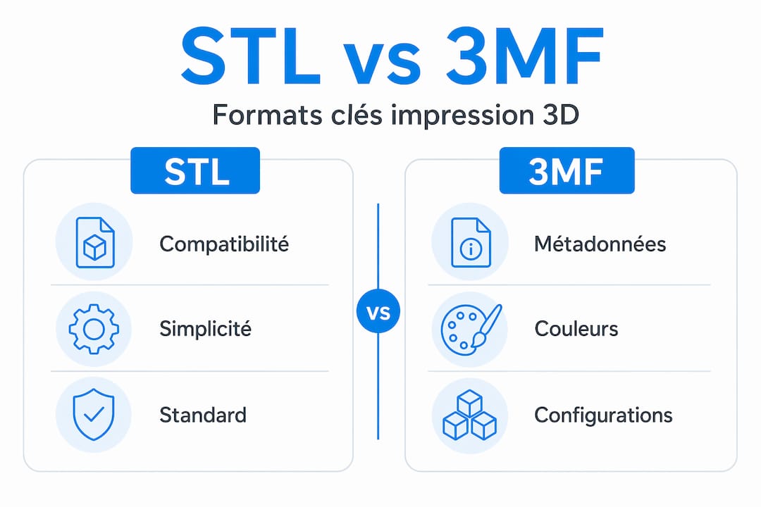
3MF brings more richness: it integrates metadata (materials, colors, units, print configuration), which significantly reduces scaling errors and simplifies multi-material workflows. For a technical part prototype or multi-color printing, 3MF is clearly superior.
STL vs 3MF Comparison
| Criterion | STL | 3MF |
|---|---|---|
| Universal Compatibility | Very High | Good (growing) |
| Color Support | No | Yes |
| Material Management | No | Yes |
| Print Metadata | No | Yes |
| Scale Error Risk | High | Low |
| File Size | Variable | More Compact |
To guide your choice: use STL for a simple prototype or when the printing service requires it. Choose 3MF whenever you work on assemblies, multi-material parts, or projects that move between multiple tools. To go further on modeling methods adapted to each format, consult our guide on efficient modeling methods.
Diagnosing and Repairing Mesh Errors
This is the step many designers underestimate. Yet, more than one in four STL files presents serious errors such as non-manifold edges or inverted normals, according to an analysis of 2,847 files. These errors directly block or compromise printing.
Here are the four key terms to master:
- Watertight: the model is closed like a solid volume, without openings. This is a necessary condition for the slicer to calculate the inside and outside of the part.
- Manifold: each edge of the mesh is shared by exactly two faces. An edge connected to three or more faces creates a geometric ambiguity that the printer cannot resolve.
- Normals: each face of the mesh has an “outward” direction. If some normals point inward, the slicer generates incorrect paths or empty zones.
- Holes: missing faces in the mesh leave openings that the slicer interprets as undefined.
Watertight and manifold geometry is essential for slicers to generate correct extrusion paths. A model that violates these rules produces either a failed print or a part with unfilled zones.
Five-Step Verification and Repair Workflow
- Export the file with a surface tolerance between 0.01 mm and 0.05 mm to balance precision and file size.
- Analyze the mesh in your tool of choice (Polyvia3D, Meshmixer, or Blender with the “3D Print Toolbox” module).
- Identify problem areas: inverted normals, non-manifold edges, open holes.
- Apply corrections automatically or manually depending on the severity and complexity of the model.
- Re-export and verify a second time before moving to the slicer.
Pro tip: For confidential files (industrial prototypes, patented parts), avoid online repair tools that store your data on third-party servers. Prefer Meshmixer, Blender, or Polyvia3D in local mode to maintain full control of your files.
Optimizing the Model Before Slicing
Once the mesh is healthy, optimizing the model itself determines the quality, cost, and printing time. This phase is often neglected by beginners, but this is where professionals make the difference.
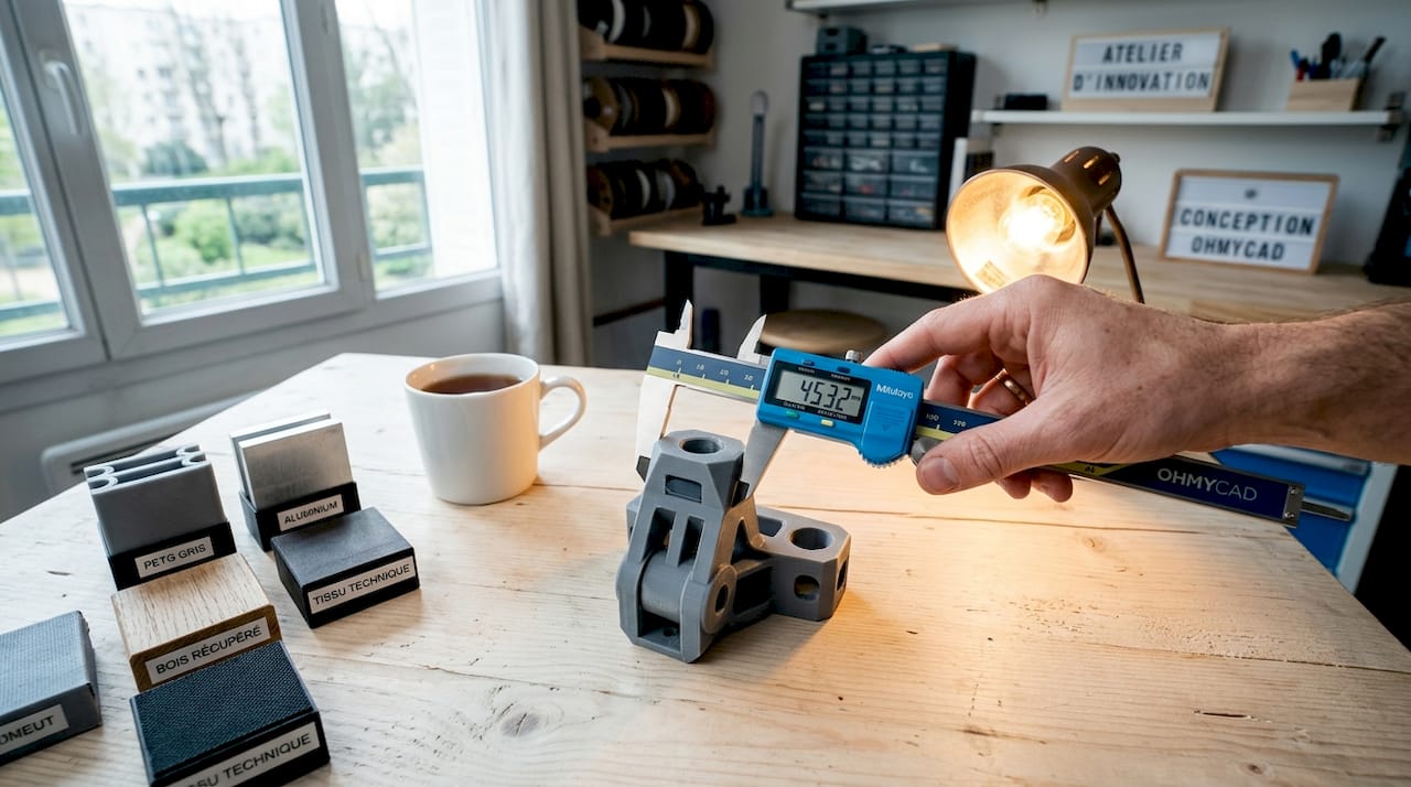
Wall Thickness and Tolerances
The minimum wall thickness depends directly on your nozzle diameter and the material used. As a general rule, a wall should be at least twice the nozzle diameter (i.e., 0.8 mm for a standard 0.4 mm nozzle). Below that, the slicer may simply ignore the wall and not print it.
Also remember to choose your material during design. PLA is easy to print, but its glass transition temperature around 50°C makes it unsuitable for parts exposed to heat or outdoors. PETG and ASA offer much better mechanical and thermal resistance for technical parts. This decision directly influences print settings, dimensional tolerances, and even part orientation.
Orientation and Support Management
Optimal part orientation reduces supports, improves dimensional accuracy, and surface quality. Here are the principles to remember:
- Overhangs less than 45° from vertical generally print without support.
- Positioning the most critical surface upward avoids support marks.
- Long, thin parts perform better upright than flat, especially for cylinders.
- The contact face with the build plate must be flat and sufficiently large to ensure adhesion.
Pro tip: Test several orientations in your slicer before starting the print. Most modern slicers (PrusaSlicer, Bambu Studio, Cura) display an estimate of the support volume generated. Choose the orientation that minimizes this volume, not just the one that seems visually logical.
Model Splitting for Complex Parts
Some complex geometries do not need to be printed in a single block. Splitting in the slicer (cut tool in PrusaSlicer, for example) allows you to print parts separately, eliminate hard-to-reach internal supports, and control assembly tolerances. This approach, well known to industrial engineers, is accessible to everyone and saves material and time. To go further, our article on 3D design optimization details concrete application cases.
Final Preparation in the Slicer
The slicer is your last safety net before printing. Use it as a validation tool, not just as a file converter.
Essential Checks
- Check scale and units: verify that the dimensions displayed in the slicer match the actual dimensions of your model. An STL file exported in inches and opened by a slicer configured in millimeters will produce a part 25 times too large or too small.
- Analyze the slicing preview: inspect layers on critical areas (overhangs, fine details, thin walls) to detect unfilled zones or aberrant paths.
- Adjust parameters according to material: nozzle temperature, print speed, layer height, and cooling vary significantly between PLA, PETG, and ASA.
- Check generated supports: ensure they properly reach areas that need them and do not interfere with aesthetic zones.
- Export in the correct format: G-code for standard FDM printers, or proprietary format for connected printers (Bambu Lab, Ultimaker S-series).
Key Parameters by Use Case
| Parameter | Rapid Prototype | Technical Part | Aesthetic Part |
|---|---|---|---|
| Layer Height | 0.2 to 0.3 mm | 0.1 to 0.15 mm | 0.1 mm or less |
| Infill | 10 to 20% | 40 to 80% | 20 to 40% |
| Perimeters | 2 | 3 to 4 | 3 |
| Supports | As needed | Minimize | Avoid if possible |
Validation in the slicer should not stop at file repair: you must confirm the final orientation and visually check each sensitive area before sending the file to the printer.
Common Errors and How to Avoid Them
Even a well-established workflow leaves room for recurring errors. Here are the warning signs and corrections to apply quickly.
- First layer not adhering: often related to incorrect scaling or insufficient contact surface. Check the bed level and increase the adhesion surface (brim or raft).
- Torn supports damaging the part: orientation is not optimal, or support separation parameters are too aggressive.
- Layer shifting: may come from a corrupted G-code file on export or a mechanical problem, but check the source file first.
- Unfilled or empty internal zones: classic symptom of a non-manifold model. Return to the mesh repair step.
- Incorrect dimensions on the final part: unit error on export or STL tolerance too high degrading the geometry.
Remember: AI-generated models frequently present non-manifold topologies, holes, and parasitic internal faces. Never send them directly to the slicer without going through a cleaning and mesh repair step.
To qualify your files before printing, the Ohmycad guide on 3D file qualification offers a structured five-step method.
My Perspective on AI Tools for 3D Preparation
By Victor
I have observed in recent years a real acceleration of AI tools applied to modeling and 3D file preparation. The promise is appealing: generate a model from an image, automatically detect mesh errors, optimize orientation with one click. And honestly, on some points, it delivers.
But here is what I have learned in practice: topology generated by AI remains imperfect for direct printing without cleaning. Raw AI models regularly contain internal faces, unclosed geometries, and non-manifold zones that automatic repair tools do not always correct properly. I have seen this on rapid prototyping projects where teams lost more time correcting AI outputs than modeling cleanly from the start.
What I recommend: use AI to accelerate creative phases and initial checks, but do not eliminate the manual mesh control step. Tools like Blender or Polyvia3D locally remain your best allies for validation before printing. Mastery of surface modeling tools continues to make the difference between a file that prints on the first try and one that requires three attempts.
— Victor
Optimize Your 3D Projects with Ohmycad
Preparing a 3D file for printing is a skill that improves with practice, but also with the right tools. At Ohmycad, we support professionals and enthusiasts in mastering the most reliable CAD solutions on the market.
The cloud-based 3DEXPERIENCE platform centralizes your CAD files, facilitates collaboration between teams, and reduces risks of errors related to multiple file versions. To go further in organizing your design data, our guide on CAD file organization gives you a clear and immediately applicable method. Contact our team for personalized support tailored to your needs.
FAQ
What format should I use to prepare a 3D file for printing?
The 3MF format is recommended for modern projects because it integrates metadata (materials, colors, units) and reduces scale errors. STL remains relevant for universal compatibility with legacy systems.
How do I detect if a 3D model is printable?
Verify that the model is watertight, manifold, and without inverted normals. Tools like Blender (3D Print Toolbox) or Polyvia3D allow you to detect these errors automatically before moving to the slicer.
Why are my dimensions incorrect after printing?
The most common cause is a unit incompatibility between the modeling software and the slicer, or an STL tolerance too high on export. Verify that your units are properly configured in both software applications.
Are AI-generated 3D models directly printable?
No. Raw AI models frequently contain topology errors (holes, internal faces, non-manifold zones) that require a cleaning and repair step before printing.
How do I reduce print supports on a complex part?
Orient the part so that overhangs remain below 45°. If the geometry does not allow it, use the cut tool in your slicer to divide the part into separately printable sections, then assemble them.