Prerequisites :
First of all, it’s important to install the software.
If you haven’t already done so, please follow this link before continuing: Install Electrical 2D and 3D
Introduction :
The process described here involves the use of several applications.
- Systems Schematic Engineer (TIC-OC): Steps 00, 01 and 03
- Electrical 3D Systems Designer (ELG-OC): Steps 02, 03 and 04
- Electrical 3D & Manufacturing Engineer (ELM-OC): Steps 05 and 06
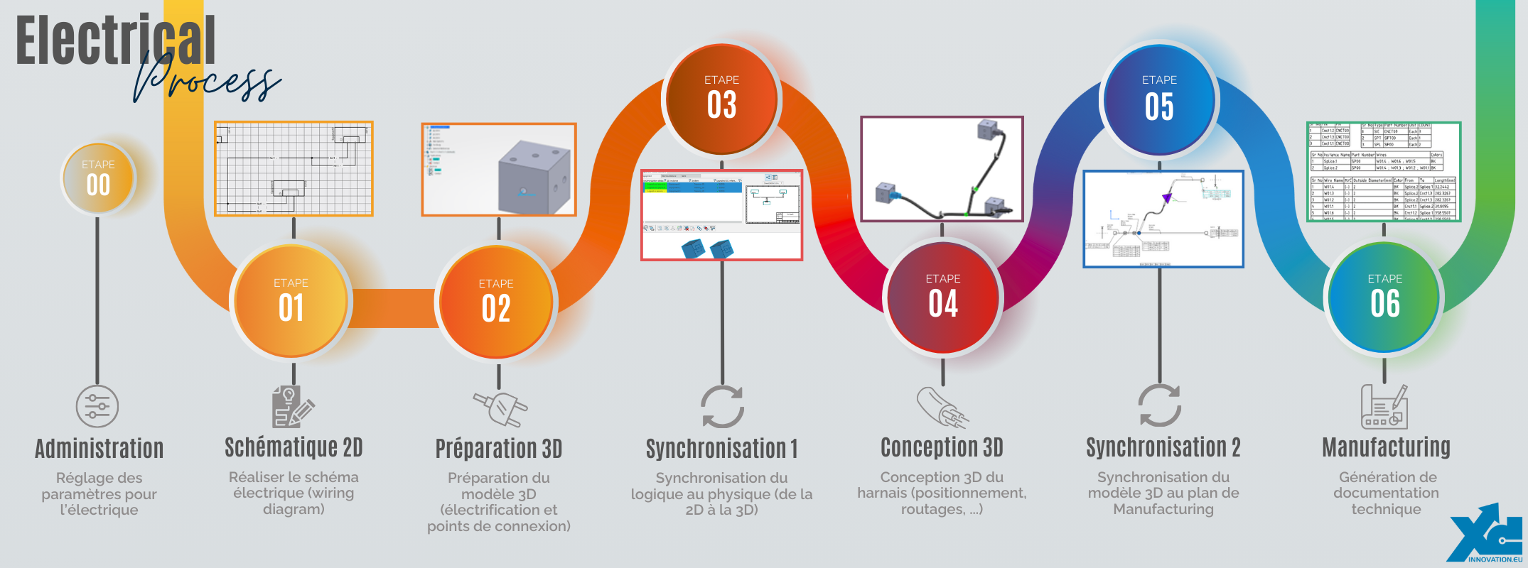
Process :
Here you’ll find a summary of each step and a link to the corresponding article.
Step 00: Setup
To start using the software with peace of mind, you need to set a number of parameters.
These can be used to manage :
- Display: symbols, cable/wire representations, etc.
- User interface: units, mouse shortcuts, grid, point magnets, etc.
- Imports of electrical resources
The aim is to make it easier for you to get started. Once you’ve got the hang of it, you’ll be able to customize it as you wish.
Link to related article: ELECTRICAL – Step 00: Parameter setting
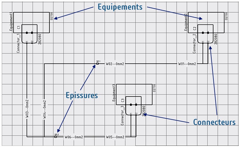
Step 01: 2D schematic
This step will enable you to create your 2D electrical diagrams.
Here you can position equipment, connectors, splices, etc. Then generate the cables and wires that connect them. You can then check that the connections between these different components have been made correctly, using control tools.
You can also define your own custom symbol libraries to best suit your sector and usage.
Links to related articles :
- ELECTRICAL – Step 01: 2D schematic (Content creation)
- ELECTRICAL – Step 01: 2D schematic (Use)
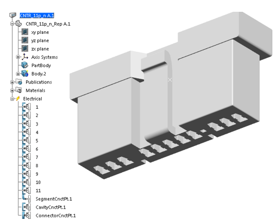
Step 02: 3D preparation
The softwareassociates a 2D component with its 3D representation. This makes it possible to synchronize electrical properties between 2D and 3D.
For this synchronization to work properly, 3D components must be electrified. Electrical properties and connection points are added to a 3D component, so that the software is able to reconnect all the elements on its own, based on the 2D schematic.
This step will teach you how to electrify your components in preparation for synchronization.
Link to related article: ELECTRICAL – Step 02: 3D preparation
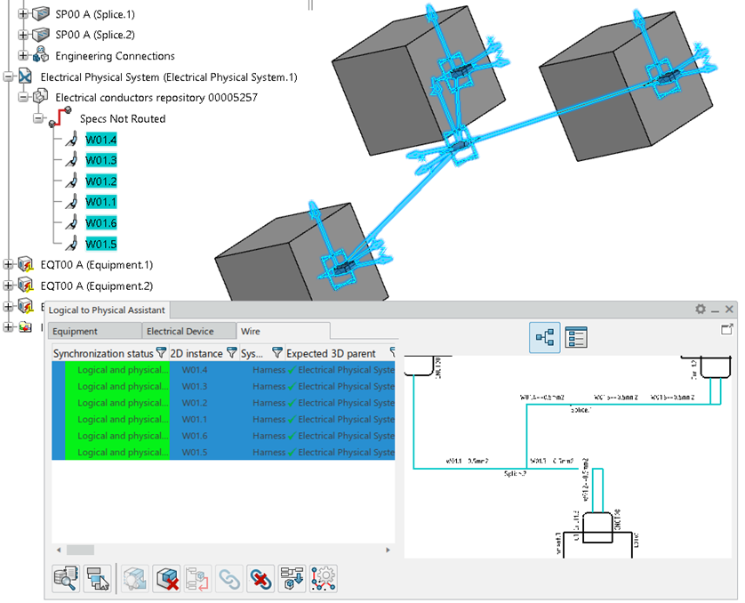
Step 03: Logical To Physical
The Logical To Physical (L2P) command synchronizes the logical and physical parts of a system, in this case a 2D schematic and the associated 3D design.
To use it, the 2D schematic and 3D design must be ready. If this is not the case, please repeat Steps 01 and 02, which are essential.
Now that everything’s ready, I invite you to follow the link to the detailed article to find out more about 2D/3D synchronization.
Link to related article: ELECTRICAL – Step 03: Synchronization 1 (“Logical to Physical” or “L2P”)
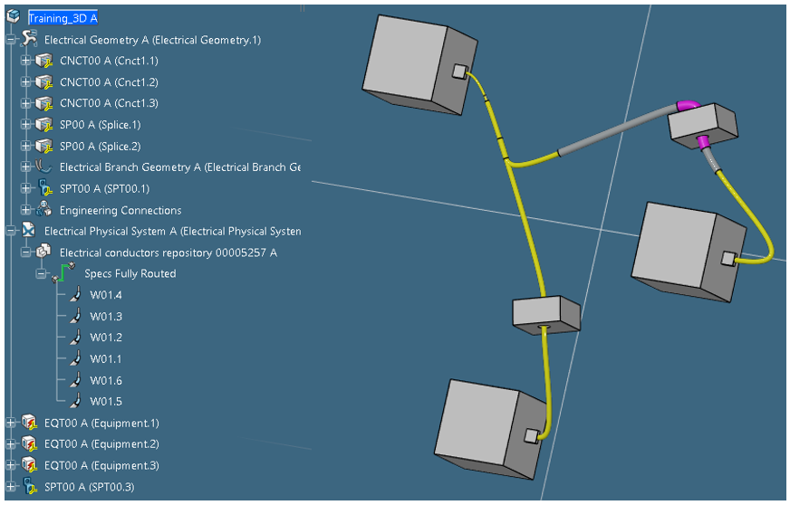
Stage 04: 3D design
Now that our 2D schematic and its associated 3D design are well synchronized, it’s time to model the complete harness in 3D. This modeling enables us to define the overall dimensions of the branches, the bending radii, the position of the supports, etc.
The initial layout is proposed by the software following the L2P command. All that’s left to do is select the specific crossing points for your design.
You’ll find all the information you need in the dedicated article.
Link to related article: ELECTRICAL – Step 04: 3D design
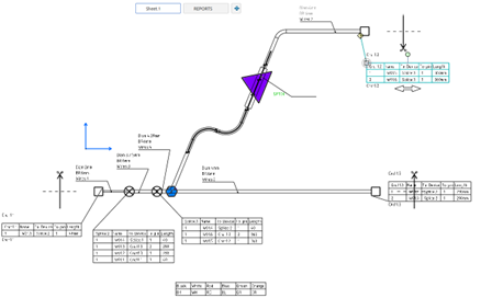
Step 05: Synchronization 2
Once the 3D harness has been defined, we’ll move on to producing the manufacturing drawings and technical documentation required for production.
The aim here is to retrieve all the information required for production (cable lengths, wire/cable type, electrical information, etc.) and to ensure that the link is made with 3D.
As with the L2P command, we’ll also make sure that drawings and documentation update automatically if a modification is made upstream.
It is also possible to simulate table-top assembly to anticipate the space and tooling requirements.
Link to related article: ELECTRICAL – Step 05: Synchronization 2 (3D to Manufacturing drawing)
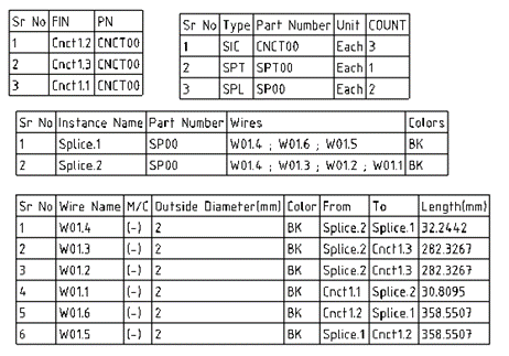
Stage 06: Manufacturing
This step is a continuation of the previous one. Once all the information has been synchronized, we generate technical documentation that complies with the standards and constraints of your industry.
To achieve the desired result, it is necessary to go through a set-up and administration phase.
Link to related article: ELECTRICAL – Stage 06: Manufacturing