- 3D file qualification prevents costly manufacturing and simulation errors.
- Key criteria include the absence of non-manifold edges, T-junctions, and self-intersecting faces.
- A structured process of verification, correction, and validation is essential to ensure CAD compatibility.
A poorly structured 3D file can halt an entire production chain. For startups and SMEs using SOLIDWORKS or CATIA, import errors, corrupted geometries, and format incompatibilities cost hours of unplanned work. Yet, the qualification of 3D files often remains overlooked, treated as a formality rather than a strategic step. This guide will walk you through, step by step, to understand why this process is essential, what criteria to check, how to proceed concretely, and how to adapt your files to the specific requirements of your CAD tools.
Table of Contents
- Why label your 3D files?
- The essential criteria for qualifying a 3D file
- 3D file validation process
- Adapt your 3D files to the requirements of SOLIDWORKS and CATIA tools
- What most users forget about qualifying 3D files
- Advanced solutions to optimize the qualification of your 3D files
- Frequently Asked Questions about 3D File Qualification
Key Points
| Point | Details |
|---|---|
| Mandatory qualification | Unqualified files lead to errors and increased costs in design and manufacturing. |
| Key technical criteria | Respect manifold rules, avoid T-junctions, and ensure CAD-ready sizes. |
| Step-by-step validation | A structured process facilitates error detection and optimizes import into SOLIDWORKS or CATIA. |
| Limited automation | Humans remain indispensable for ensuring file quality, even with good automated tools. |
Why label your 3D files?
Working with unqualified 3D files is like navigating without a net. The consequences are rarely visible at first, but they add up quickly. A model with poorly defined surfaces might import without apparent errors, only to cause a crash during simulation or generate unusable parts in additive manufacturing.
Here are the most frequent problems related to a lack of qualifications:
- Massive time wastes Manual correction of errors during a project, often discovered too late.
- Manufacturing defects A corrupted STL file sent to a 3D printer or machining center produces non-conforming parts.
- CAD incompatibilities : A STEP file imported into SOLIDWORKS with missing faces causes a display issue in SOLIDWORKS that is difficult to diagnose.
- Simulation Stalls FEA and CFD solvers reject imperfect geometries or produce erroneous results.
- Friction in collaboration When multiple teams share files, heterogeneous geometry creates interpretation discrepancies between sites or partners.
The impact is even more pronounced in advanced manufacturing contexts. In CNC machining, a self-intersecting surface can generate incorrect tool paths. In multiphysics simulation, a mesh based on faulty geometry falsifies all the results. The unqualified models present structural irregularities and lead to interpretation errors that propagate to all subsequent stages.
For distributed teams, file consistency is even more critical. When an engineering office in France shares an assembly with a subcontractor in Asia, any geometric ambiguity turns into delays or non-compliance.
“The qualification of 3D files is not a technical option, it is a condition for success for any serious industrial project.”
Pro tip: Incorporate a systematic verification step upon receiving any external file, even before opening it in your CAD environment. This prevents contaminating your assemblies with defective geometry.
The essential criteria for qualifying a 3D file
Qualifying a 3D file means ensuring it complies with a set of precise geometric and dimensional rules. These criteria are not arbitrary: they reflect the requirements of the calculation engines used by SOLIDWORKS, CATIA, and digital manufacturing tools.
The main geometric defects to detect are:
- Non-manifold edges an edge shared by more than two faces. This type of error is invisible to the naked eye but blocks any meshing process.
- T-junctions T-junctions between surfaces, which create geometric discontinuities incompatible with most solvers.
- Self-intersecting faces surfaces that intersect themselves, making the volume ambiguous for the software.
- Slivers (degenerate faces): extremely thin or elongated faces that disrupt calculation algorithms.
- Inverted normals : faces with incorrect orientation, which disrupts display and simulation.
To be valid, a file must respect the manifold rule, avoid T-junctions, and ensure dimensions are consistent with the target tool tolerances within the specified minimum and maximum limits.
| Criterion | Recommended value | Impact if not respected |
|---|---|---|
| Minimum dimension | 0.01 mm | Mesh or import error |
| Maximum dimension | < 2,000 mm | Solver limits exceeded |
| Non-manifold edges | 0 | Simulation/Manufacturing Block |
| Self-intersecting faces | 0 | Incorrect simulation results |
| Consistent normals | 100 % | Incorrect display and rendering |
These criteria apply regardless of the file format. Whether you are working in STEP, IGES, or Parasolid, the fundamental geometric rules remain the same. To learn more about best modeling practices, our 3DEXPERIENCE 3D Design guide Detail the standards to adopt from the design phase.
Pro tip: During a quick analysis, focus first on non-manifold edges and self-intersecting faces. These are the two most frequent and blocking types of errors in a professional CAD workflow.
3D file validation process
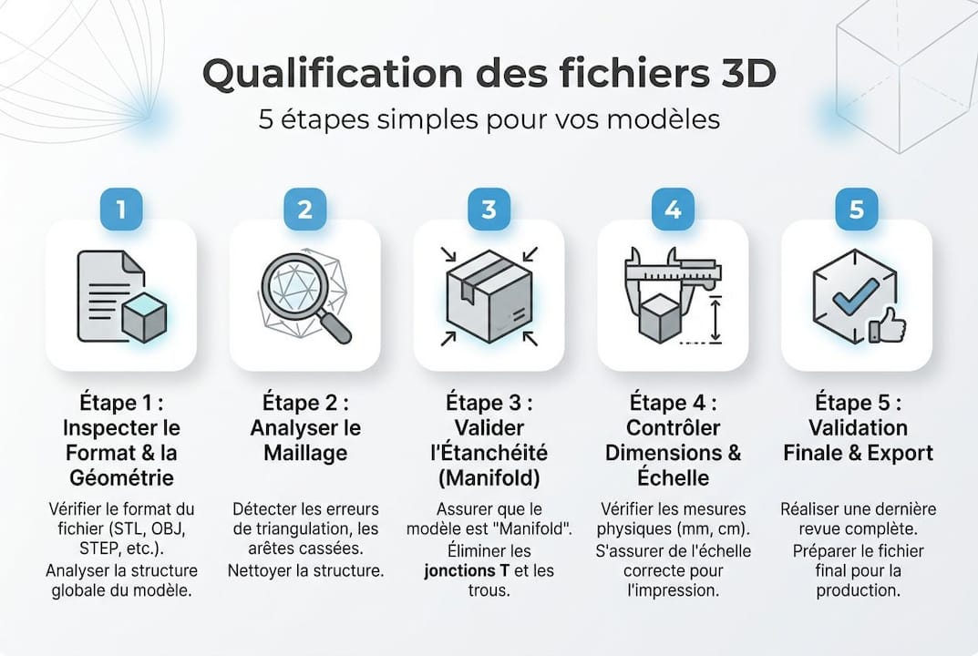
With the criteria clearly identified, let's move on to the concrete method. Validating a 3D file cannot be improvised: a structured approach saves time and avoids cascading corrections.
Recommended validation steps:
- Controlled import Open the file in a neutral validation tool (MeshLab, Netfabb, or your CAD software's native diagnostic module) before integrating it into an assembly.
- Automatic error analysis Run a full diagnostic to identify non-manifold edges, degenerate faces, and normal inconsistencies.
- Automated correction Use the built-in repair tools for simple errors (inverted normals, small holes).
- Manual correction : for complex errors like T-junctions or slivers, manual intervention often remains necessary.
- Dimensional Check Ensure that the dimensions are within acceptable ranges for your target workflow.
- Final import Test Re-import the corrected file into SOLIDWORKS or CATIA and check for warnings.
Geometry validation must be performed before any FEA/CFD simulation or move to manufacturing, without exception. Incorporating this step early in the process prevents costly rework. For projects involving fluid simulation in CAD, geometric accuracy is particularly critical because CFD solvers are highly sensitive to surface imperfections.
| Tool | Type | Strengths | Limits |
|---|---|---|---|
| Native SOLIDWORKS Diagnostics | Integrated | Fast, no export | Less precise with complex meshes |
| Netfabb | Specialized | Advanced Car Repair | Less intuitive interface |
| MeshLab | Open source | Fine mesh analysis | No auto-repair |
| CATIA DMU | Integrated | Suitable for large assemblies | For advanced licenses only |
For teams managing many assemblies, consider consulting our resources for optimize SOLIDWORKS assemblies and reduce processing times.
Pro tip: To quickly detect non-manifold edges in SOLIDWORKS, enable the “Check” option in the Tools menu and filter the results by error type. You can identify problematic areas in under two minutes on most models.
Adapt your 3D files to the requirements of SOLIDWORKS and CATIA tools
Once the file is geometrically validated, you must ensure that it is compatible with the target CAD tool. SOLIDWORKS and CATIA have specific requirements in terms of import formats and parameters.
Recommended formats by usage:
- STEP (AP203/AP214) Universal format, recommended for inter-software exchanges. Very well supported by SOLIDWORKS and CATIA.
- Parasolid (.x_t, .x_b) : SOLIDWORKS native format, offers the best geometric fidelity for exchanges between software based on the Parasolid kernel.
- IGES Older format, to be used only when STEP is not available. Less reliable for complex surfaces.
- CATPART / CATPRODUCT CATIA native formats, to be used as a priority in a pure Dassault Systèmes environment.
- 3DXML light format for visualization and sharing, without the full design data.
Correcting the geometry to meet CAD software requirements prevents 90% of import or simulation failures, resulting in significant time savings over the course of a project.

To automate conversions, tools like Datakit or 3DTransVidia allow for batch processing of files with pre-configured conversion profiles for SOLIDWORKS or CATIA. This drastically reduces manual intervention on high-volume projects.
Also keep metadata management in mind: a well-qualified file includes revision information, units of measurement, and tolerances. Coding with 3DEXPERIENCE allows you to structure this information in a systematic and traceable way.
To remember: Always adhere to the dimensional constraints (minimum 0.01 mm, maximum 2.000 mm) and use the STEP format for external exchanges. These two simple rules eliminate most import issues.
What most users forget about qualifying 3D files
Our field experience with SMEs and startups reveals a recurring mistake: believing that automatic repair tools are sufficient. They are useful, but they do not replace human judgment.
An automated tool can fix an inverted normal in seconds. But it doesn't know if a degenerate face is the result of a modeling error or an intentional design choice. In the latter case, automatic correction can introduce an invisible functional error.
Project context is extremely important. A file intended for additive manufacturing does not have the same requirements as a file for FEA simulation. Applying the same qualification rules indiscriminately sometimes leads to over-correction and degradation of model accuracy.
We always recommend a human review after any automated correction, especially for critical functional parts. Advanced design requires a combination of powerful tools and business expertise. One without the other is taking a risk that SMEs' deadlines and budgets cannot always absorb.
Advanced solutions to optimize the qualification of your 3D files
You have now mastered the fundamentals of qualification. The next step is to implement a reliable and reproducible process in your organization.
At Ohmycad, we support startups and SMEs in implementing robust CAD workflows, from file qualification to product data management. Our solutions include access to CAD Cloud 3DEXPERIENCE to centralize and secure your qualified files, as well as tools for 3D CAD visualization to visually validate your models before production. To take your project presentations to the next level, check out our resources on SOLIDWORKS photorealistic rendering. Contact our team for a personalized assessment of your current workflow.
Frequently Asked Questions about 3D File Qualification
What common errors prevent a 3D file from qualifying?
The most blocking irregularities are non-manifold edges, T-junctions, and self-intersecting surfaces, which make the model unusable for simulation or manufacturing.
How to verify that the model size meets the CAD tolerances?
Make sure that the minimum dimension is greater than 0.01 mm and that the maximum dimension is less than 2,000 mm, two critical thresholds for compatibility with CAD solvers.
Is it possible to automate the qualification of 3D files?
Many tools offer partial automatic correction, but manual validation remains essential for complex or functional parts.
Why are qualified 3D files vital for FEA/CFD simulation?
They guarantee mesh integrity and prevent crashes: FEA/CFD validation before manufacturing is an essential prerequisite for obtaining usable and reliable results.
Recommendation
- 2. File Encoding with 3DEXPERIENCE – Ohmycad | SOLIDWORKS Partner
- Types of 3D visualization: A complete guide for CAD
- 1. Share 3D files via a direct link – Ohmycad | SOLIDWORKS Partner
- 3D Design Guide: Mastering 3DEXPERIENCE in 2026