Here are a few parameters to set to prepare your working environment.
Prerequisites (for each PC) :
To complete the rest of this tutorial, you will need the following items:
- Licenses :
- Systems Schematic Engineer (TIC-OC)
- Electrical 3D Systems Designer (ELG-OC) OR Electrical 3D & Manufacturing Engineer (ELM-OC)
- Authorization: Owner and Manager of the collaboration space
GVS :
GVS stands for “Generative View Style”.
Generative view styles are defined by an administrator and specify the display and behavior of a generated view. To find out more, go to: About generative view styles
Place the following folder in a folder to which you have rights (such as “Desktop” or “My Documents”)
CATEnv :
The Env.txt file defines all the environment variables used by the software. It may differ from one PC to another, depending on user preferences.
Path : C:\Program Files\Dassault Systemes\B4xx_Cloud\CATEnv
(Replace B4xx with the latest version on your PC)
- Make a copy of Env.txt
- Open the original file with Notepad++ in “Administrator” mode
- Search for variable CATCollectionStandard=
- Enter as value the path defined for the GVS folder: CATCollectionStandard=C:\Users\Maude\Desktop\GVS
Watch out!
- Do not modify fields in the Env.txt file unless prompted to do so.
- Always keep a copy of the original file for safekeeping
Video tutorials :
Explore the Systems Schematic Engineer Role
Lesson: Prepare the Environment
Preferences :
To access preferences, click on your initials in the top right-hand corner.
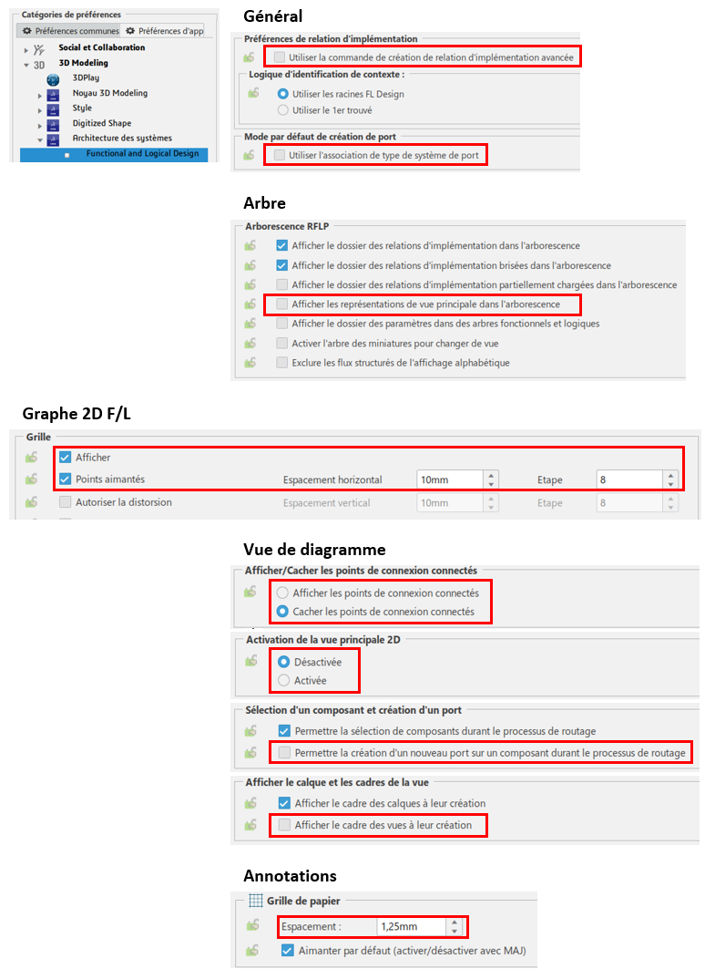
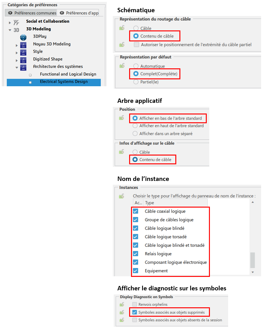
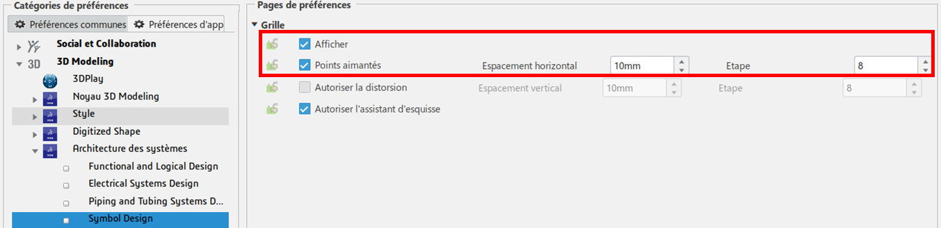
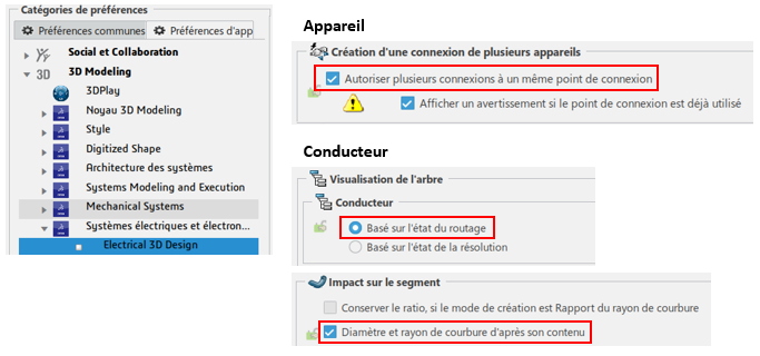
Once the window is open, make sure your settings are identical to those below:
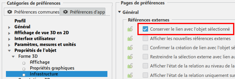
General :
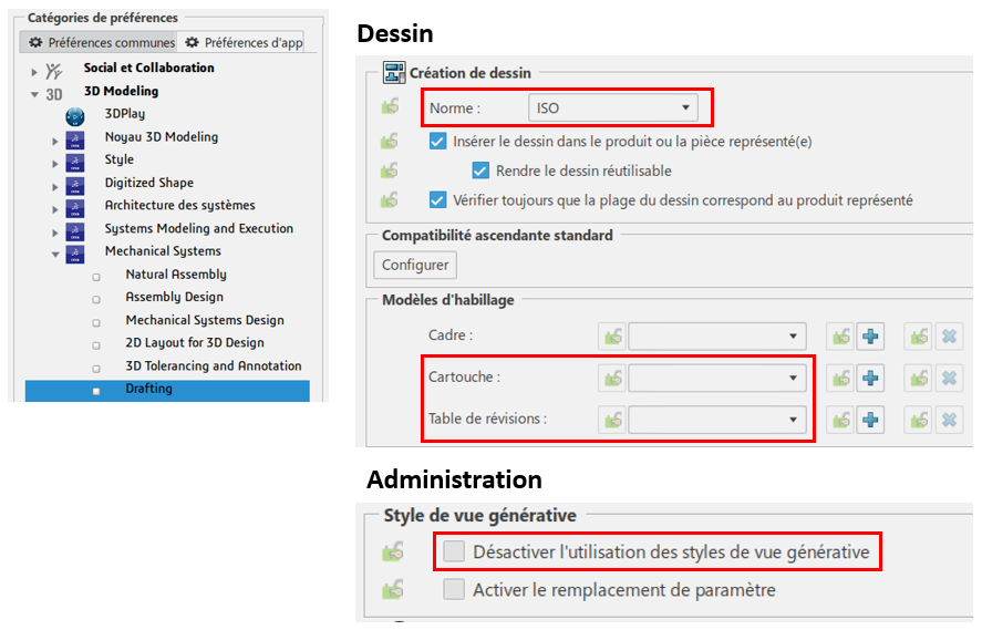
Mechanical :
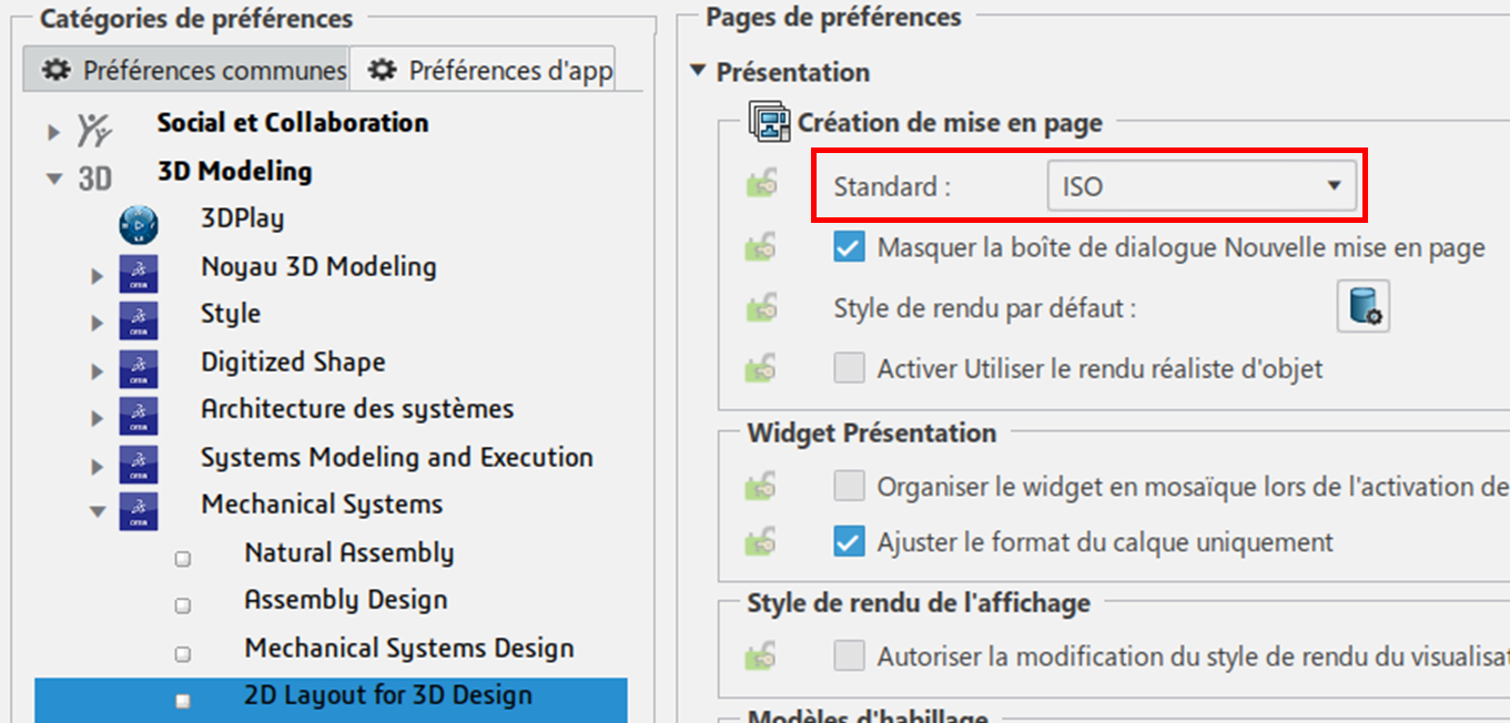
Electric :
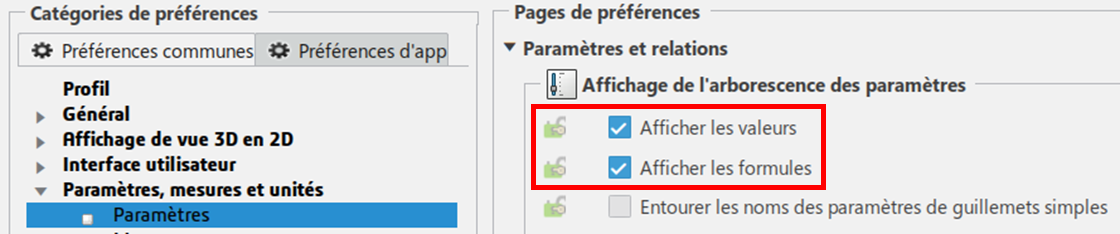
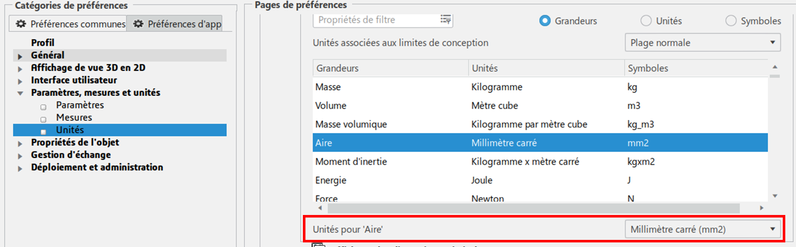
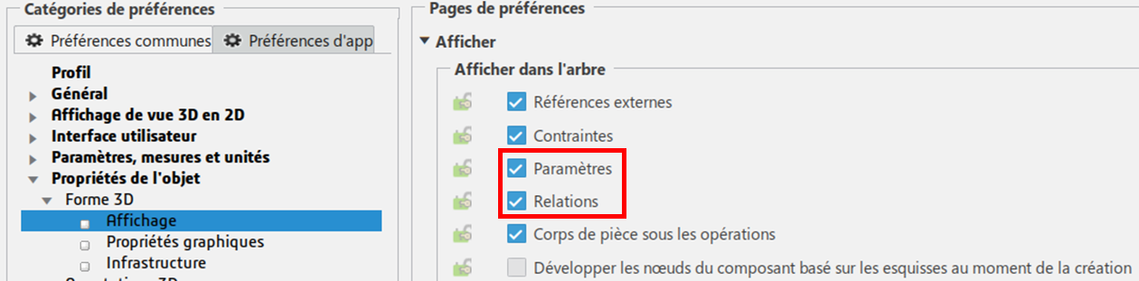
Creation and display parameters :
First, let’s set up component creation:
- Click on “+” then “New content”.
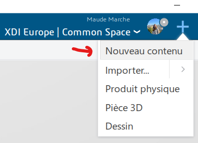
- Then click on “Define attributes at creation time for all types”.
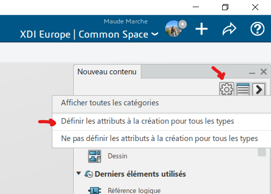
- Close tab without saving
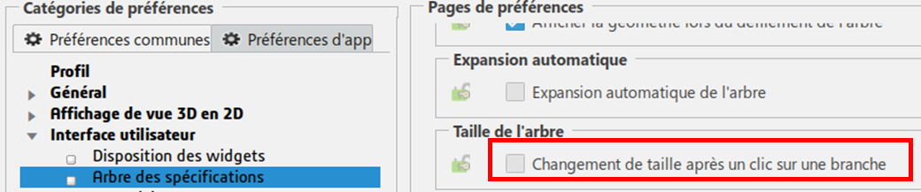
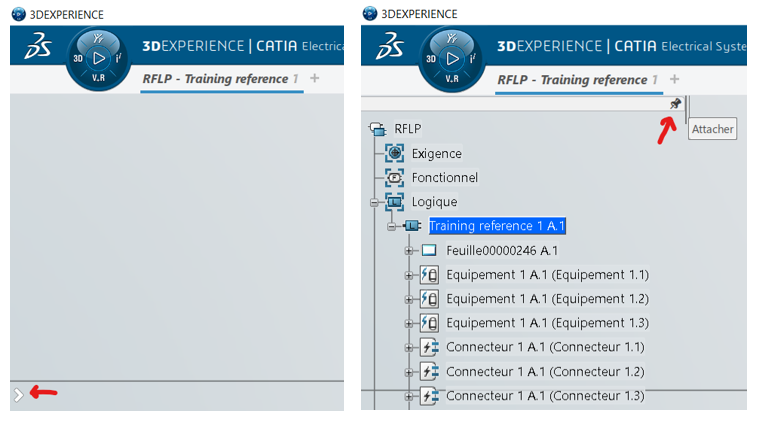
Then, for the sake of comfort, I encourage you to fix the tree view so that it remains displayed:
Resources :
If you have Mechanical and Electrical users, we recommend that you create 2 separate collaboration areas.
Resources enable the software to react in a specific way when a particular function is used. They are grouped into “resource sets” according to the elements on which they act.
To get you off to a good start, we provide you with an initial dataset containing predefined symbols, rules and resources.
You are then free to modify and/or replace them with other personalized content.
Import :
Here’s how to import this data correctly into the 3DEXPERIENCE platform:
- Launch software
- Click on “+” then “Import…”.
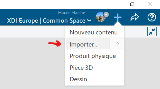
- Select the file to import
- Make sure the “New” option is checked, then import.
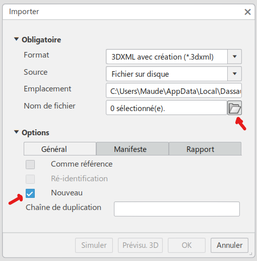
- Repeat for all 8 files in the folder
Configuration :
Once imported, you now need to define in the software which set of resources to refer to in the various use cases. Here’s how to do it:
- Ensure “Owner” status
- Open the “Data Setup” application
- The application is divided into two panels:
- Left: a list of the different collaboration spaces and the resource sets currently in use in each.
- Right: Complete list of available resource packs, sorted by section
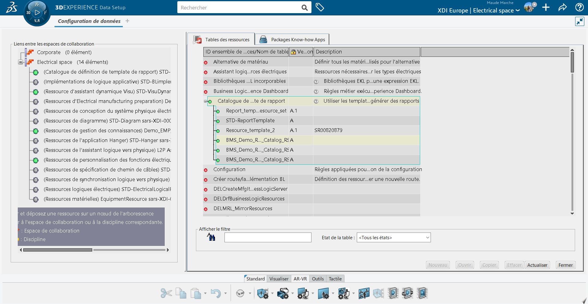
- Drag and drop the 8 imported resource sets from the right panel to the collaboration space in the left panel.
- The sections in which resource sets are stored (right-hand side panel) are displayed in brackets in the left-hand panel.
- Save data configuration
The 4 steps to modifying the Data Setup :
- Create or import resource
- Place the resource with its criteria in the resource set
- Link to a collaborative workspace
- Save
Catalog :
One of the available resources contains a catalog of standard elements.
On loading, the platform automatically adds a number to the end of each element’s name to make it unique.
We’re going to rename these elements to make them easier to use on a daily basis.
- Open Data Setup
- Right-click to edit the BMS_Demo_EMP_RS resource set
- Right-click on the Catalog (line 1) and open it
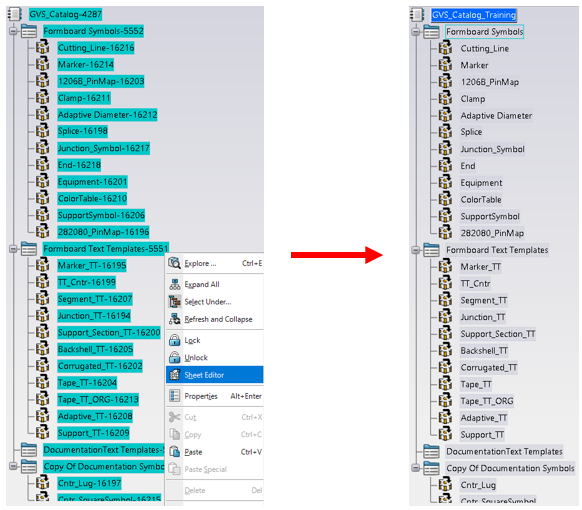
- Expand all catalog lines, select with Ctrl+Shift
- Right-click and use the “Folio editor” command
- Rename all components by removing the number at the end
The goal is to achieve this result:
And then…
Once all these steps have been completed, it’s time to get down to business:
Step 01: 2D schematic
Step 02: 3D preparation